
Japtastic
New member
Hi, I'm fairly new to logic board repair and schematic reading / electronics although I have been in the IT repair business for the last 20 years.
I'm trying to work out my first logic board repair and may well have got confused along the troubleshooting route. Could do with a helping hand!
These are my test results / notes:
PPDCIN_G3H = 14.8v SCHEMATIC SAYS 18.5v ??
PPBUS_G3H = 8.35v SCHEMATIC SAYS 8.4V
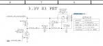
PP3V42_G3H = 3.29v SCHEMATIC SAYS 3.42v
PP3V3_S5 = 3.2v SCHEMATIC SAYS 3.3v
PP3V3_S3 = -- SCHEMATIC SAYS 3.3v
PP5V_S3 = -- SCHEMATIC SAYS 5v
R7910 Pin1 = 3.26v Pin2 = 3.11v 47k ohm tested ok
C7911 Pin1 = 3.29v Pin2 = 3.17v
C7910 Pin1 = 3.1v Pin2 = 0v
Q7903 Pin1 = 0v Pin2=G Pin3 = 3.25v
Q7910 Pin 4 = 3.29v Pin 3 = 3.11v Pin1,2,5,6 = 0v
There is no obvious water damage to the board and everything looks great and very clean.
Am I right in thinking the next step is to replace Q7910?
Of course, I could be mis-reading the schematic entirely and have the completely wrong end of the stick...
Cheers
Stewart
I'm trying to work out my first logic board repair and may well have got confused along the troubleshooting route. Could do with a helping hand!
These are my test results / notes:
PPDCIN_G3H = 14.8v SCHEMATIC SAYS 18.5v ??
PPBUS_G3H = 8.35v SCHEMATIC SAYS 8.4V
PP3V42_G3H = 3.29v SCHEMATIC SAYS 3.42v
PP3V3_S5 = 3.2v SCHEMATIC SAYS 3.3v
PP3V3_S3 = -- SCHEMATIC SAYS 3.3v
PP5V_S3 = -- SCHEMATIC SAYS 5v
R7910 Pin1 = 3.26v Pin2 = 3.11v 47k ohm tested ok
C7911 Pin1 = 3.29v Pin2 = 3.17v
C7910 Pin1 = 3.1v Pin2 = 0v
Q7903 Pin1 = 0v Pin2=G Pin3 = 3.25v
Q7910 Pin 4 = 3.29v Pin 3 = 3.11v Pin1,2,5,6 = 0v
There is no obvious water damage to the board and everything looks great and very clean.
Am I right in thinking the next step is to replace Q7910?
Of course, I could be mis-reading the schematic entirely and have the completely wrong end of the stick...
Cheers
Stewart
Attachments
Last edited: