Very new to board repair
Green Light on charger
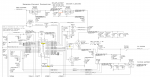
Decided to start with U7000
R7020: 0 VOLTS
PPDCIN_G3H: 18.5V
Q7080: SOURCE: 18.5V GATE: 17.88 DRAIN: 18.03
Q7085: SOURCE: 18.03V GATE: 17.23 DRAIN: 0V
R7085 actually sparked when I tested it
R7020: 0 VOLTS (PPBUS_G3H_DCINRUSH)
U7000: RESISTANCE PINS 27-28 20.3 OHMS (CURRENT SENSING)
F7040 Fuse: pin 2: 0 V (starts at 1 and slowly drifts to 0)
U7000
PIN 14: SMC_BC_ACOK: 3.27V
PIN 19: 5.1 V
My thought is that Q7085 is bad. Should have voltage going through it. Without that, no PPBUS_G3H
Am I on the right track?
Green Light on charger
Decided to start with U7000
R7020: 0 VOLTS
PPDCIN_G3H: 18.5V
Q7080: SOURCE: 18.5V GATE: 17.88 DRAIN: 18.03
Q7085: SOURCE: 18.03V GATE: 17.23 DRAIN: 0V
R7085 actually sparked when I tested it
R7020: 0 VOLTS (PPBUS_G3H_DCINRUSH)
U7000: RESISTANCE PINS 27-28 20.3 OHMS (CURRENT SENSING)
F7040 Fuse: pin 2: 0 V (starts at 1 and slowly drifts to 0)
U7000
PIN 14: SMC_BC_ACOK: 3.27V
PIN 19: 5.1 V
My thought is that Q7085 is bad. Should have voltage going through it. Without that, no PPBUS_G3H
Am I on the right track?