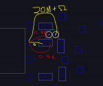
820-3476 pp5v issues (Orange light, no sound/video)

Monkey Bytes

New member
I have an 820-3476 Board with supposedly no water damage. I cleaned some corrosion from inside the thunderbolt ports. I found some corrosion near one of the debug connectors, so I removed it. Later I thought it may be a BIOS Issue so I replaced the bios chip.

Initially this board had an orange light (no battery), and the fan would power on for a second or two, turn off, and then repeat. I searched the board and found that the S5 rails were constant while the S0 rails were ALL turning on and off. Otherwise those rails seemed to be exactly as expected. I've checked every current sensing resistor I could find, thinking it was a sensor issue. After a week or so of troubleshooting, the fan no longer spins up. I left it whilst doing the spin-up routine for 10 minutes, came back, and now I'm here.

PPBUS_G3H is 12.5V along with all the ppbus_s5 rails.
pp5v_s0 0v
pp5v_s5 0.9v
pp3v42_g3h 3.41v


The weirdest thing that made me sign up for this forum is that the F7005 18.5V fuse has 0.1ohm resistance, yet has 0V on both sides when plugged in. If I test the pins on the DC Jack connector, they all come back as 0 volts. So either something is terribly wrong or I might just have the secret for infinite energy.

Any advice? I'm now looking to troubleshoot the ISL6259 circuitry to see if maybe it's responsible for my pp5v_s5 problems.

I have the board view, schematic, a donor board, a basic microscope/iron/air station and so forth.
 
Last edited:

dukefawks

Administrator
It is of course not possible to have PPBUS_G3H and not have power going in to F7005, assuming you have no battery plugged in. Go back and check again.
 

Monkey Bytes

New member
Alas, the screw hole I was using as a ground was not properly grounding! The fuse has voltage (16.5v)
Still, pp5v_s5 is .105v
pp5v_s0 is missing.
pp3v3_s0 is .105v
pp1v05_s0 is missing
pp5v_s4 is 0.415v
ppbus_s5_hs_computing is 12.5v

I see that u7200 seems to input ppbus_s5_hs_computing and outputs pp5v_s0
u7200 VIN is 12.5v, yet VDD is 0v

so is ISL95826 potentially bad? Or are there any major other sensors I should first investigate?
 

Monkey Bytes

New member
Resistance to GND on PP5V_S5? If not low then TPS51980 is dead.
Resistance appears to be huge, and measuring capacitance shows ~10uF (same as C7505). So should I run a wire from C7505 to pin 29 on TPS51980?

I replaced TPS51980 from a donor and got the same result except that pp5v_s5 was 1.4V.

Re-seated the chip for good measure and now it's doing what it was doing before (fan stops and starts). The resistance of pp5v_s5 is now 1.9M ohm.

PP5v_s0 and all other s0 rails appear to be pulsing along with the fan. This was the original issue before I lost pp5v_s0 altogether.


If you think TPS51980 from donor is bad (only revived by heating) then I can order some "new."
 
Last edited:

Monkey Bytes

New member
Okay So pp3v3_s0 is pulsing, pp5v_s0 is constant, as is pp3v3_s5. So the 3.3v/5v power supply is functioning correctly.
This board doesn't have a 3.3v current sensing circuit, so perhaps the switching circuit - if it has one?
I am aware that quarter fan spin is probably the most annoying to troubleshoot, and I've watched all rossmann videos regarding it.

Does this seem like an RTC issue? There was initially a small amount of liquid damage on the edge of the board that contains 3 RTC crystals, along with one of the diagnostic connectors, which I had removed. Unfortunately I do not have an oscilloscope to test the clock signals.
 

Monkey Bytes

New member
Check the resistors that are in series with the data lines to the SPI ROM, all 8 of them.
All resistors in the SPI Bus Series Termination section are as expected (33ohm or ~0-0.2ohm).
R6101 on the SPI ROM section is showing 0.8K instead of 3.3k, however replacing the resistor from donor yields the same result (tests 3.3k out of circuit), however, the same resistor tested at 3.3K in circuit on the donor. So the SPI rom has a resistance of only 0.786K between pins 8 and 3.
 

dukefawks

Administrator
First post says you replaced BIOS chip, what file did you flash to the chip?
You should put back the original in any case. When you have the chip out measure on diode mode all 4 data pins, 1,2,5 and 6. This way you can check if the trace to the CPU/PCH is ok and the resistors too.
 
Last edited:

Monkey Bytes

New member
First post says you replaced BIOS chip, what file did you flash to the chip?
You should put back the original in any case. When you have the chip out measure on diode mode all 4 data pins, 1,2,5 and 6. This way you can check if the trace to the CPU/PCH is ok and the resistors too.

I personally did not flash anything to the ROM. I purchase them pre-flashed for this particular model. Same way I normally remove EFI lock.
And I may have fucked up and lost the original ROM chip. I'll see if I can find it.
Continuity from pin to nearest component checks out on all pins. Pins 1, 5, and 6 give me ~1.3V in diode mode. Pin 2 gives me a little under 1.0V.
 

Monkey Bytes

New member
Do not ever replace ROMs like that, this will fuck up the ME region and cause all sorts of problems.
Understood. I'd still like to fix the board, even if the PCH throws a fit. This is still the same issue previously experienced using the original ROM.
Any general direction you can suggest? I am willing to waste a dozen hours studying but I am unsure which processes/chips to investigate for this Problem.
 

dukefawks

Administrator
I'd be worried about that measurement on R6101. Only cause for that would be a bad ROM chip. Remove and measure data lines and find the original.
 

Monkey Bytes

New member
No Title

I'd be worried about that measurement on R6101. Only cause for that would be a bad ROM chip. Remove and measure data lines and find the original.
When I've removed the ROM, the measurement is the same: about 0.8K. I physically remove r6101 and it tests at 3.3k out of circuit. I test resistance of the r6101 pins on the board and my multimeter is overloaded.

Here are some of the measurements I have made. R6103 (in circuit) and R6101 (out of circuit) appear to be correct. C6100 appears to be 'charging' as does any capacitor. So maybe the traces within the board are fucked up?
 

Attachments

  • photo420.PNG
    photo420.PNG
    67 KB · Views: 0
Last edited:

dukefawks

Administrator
Is R6130 present on the board?

Hmm guess not cause the R6101 would not be there, R6130 is only if ROM supports quad SPI mode!

Well, if you removed the ROM then there is nothing else connected to R6101 and it MUST measure 3.3K. Check R6130 position for crap otherwise the issue must be inside the board.
 
Last edited:

Monkey Bytes

New member
Is R6130 present on the board?

Hmm guess not cause the R6101 would not be there, R6130 is only if ROM supports quad SPI mode!

Well, if you removed the ROM then there is nothing else connected to R6101 and it MUST measure 3.3K. Check R6130 position for crap otherwise the issue must be inside the board.

Hmm. Maybe too much lead in my diet.

When originally replacing the ROM (first thing I tried, before joining this forum), I shifted some things around and I thought I had blown one of those components off the board. One of them, either R6101 or R6130, I noticed was completely missing! So I grabbed one and replaced it thinking I was fixing my fuck-up.

So most recently I've tried removing R6101. Same issue. I've then replaced R6101 and removed R6130. Same issue - albeit R6101 correctly measures 3.3k.
So I've lost the original ROM and the schematic doesn't specify whether or not the board has quad SPI.

Meanwhile I'm going to be comparing with the donor to see if there's anything else I might have wrongly screwed with.

The biggest and only clue I have for this board was corrosion in the thunderbolt and USB ports. Is there a way to isolate that portion of the board? Just disconnect a resistor or fuse somewhere to cut them out of the equation so I can see if the core of the board is able to boot on its own? The Thunderbolt 15V boost regulator circuit outputs 0v, but I don't know when or if thunderbolt is expected to initialize.
 
Last edited:
Top