MacBook M1 Pro 14" 2021 A2442 (820-02098) — U2020 getting hot, board not powering on

slimmy182

Member
Hi all,

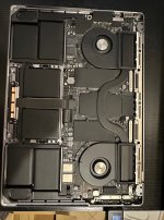
I’m working on a MacBook Pro 14” 2021, board 820-02098, no power.
I’ve been focusing on the PP1V8_AWAKE rail which seems problematic.
Here is what I’ve tested:

    • Symptoms:
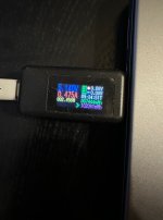
      • Board does not power up.
      • Power-in: ~5.1 V / 0.47 A (~2.45 W)
      • With thermal camera, U2020 was initially hot (>70 °C).
    • Measurements:
      • Resistance to GND @ C2021 / C2030 / C2041 = ~4.0 Ω (meter probes zeroed).
      • Same reading in diode mode.
      • Voltage with board powered:
        • PP1V2_AWAKE = 1.2 V (OK)
        • PP1V8_AWAKE = only ~1.55 V instead of 1.8 V.
    • Isolation steps:
      • Removed bulk caps C2021, C2030, C2041, C2010 → resistance unchanged (~4 Ω).
      • Removed U2030 & U2040 (SN74AVC1T45 level shifters) → unchanged.
      • Removed U2020 → unchanged.
      • Removed LR501 / LR502 → codec side high resistance, but PP1V8_AWAKE side still ~4 Ω.
      • Injected 1.5 V / 3 A at C2041: current flows, but no clear hotspot. (did not sink the full 3 A – the power supply stayed in CV mode with around 0.4 A draw)
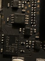
        • Only U2010 (MX25U6472F SPI flash) warms slightly (~40 °C).
      • U2000 (second SPI flash) not yet removed.
      • Other caps tested/removed → no change.
    • Current status:
      • PP1V8_AWAKE undervolts to ~1.55 V.
      • Rail resistance still ~4 Ω.
      • Only U2010 shows activity under injection (light heating).

    • After removing U2010, the resistance on PP1V8_AWAKE → GND increased from ~4 Ω to ~8 Ω.
    • Power injection at 1.5 V/ 3 A at C2041→ ~0.15A (CV), no visible hotspot (thermal + IPA).
    • U2010 off-board: VCC–GND ≈ 6 Ω → clearly leaky; will replace.
    • U2000 off-board measured high resistance; reinstalled → rail still ~8 Ω.
 

Attachments

  • 534765781_24222787390749756_1323272943338294397_n.jpeg
    534765781_24222787390749756_1323272943338294397_n.jpeg
    414.1 KB · Views: 0
  • 535803408_24222787427416419_4621403402130419085_n.jpeg
    535803408_24222787427416419_4621403402130419085_n.jpeg
    692.6 KB · Views: 0
  • 536275461_24222787397416422_8976995675091478075_n.jpeg
    536275461_24222787397416422_8976995675091478075_n.jpeg
    408.7 KB · Views: 0
Last edited:

2informaticos

Administrator
Staff member
"Injected 1.5 V / 3 A"
Can you explain how did that???
You can claim for Nobel prize!

1.5V divided by 4 ohm let you with just 375mA.
Read something more about Ohm law...

0.368 listed for diode mode on refference table.

Voltage injection can't cause important heat.
Remove CPU heatsink first, then use performant thermal camera.
Any chip, or capacitor showing a bit more heat signature like the rest, is suspect.

BTW, when you inject voltage, set current limit to max from start.
The board will take just the current required by the resistance to ground; you can't adjust it.
 

slimmy182

Member
Thanks for the comment. We’re on the same page with Ohm’s law.
  • Earlier, before removing U2010, PP1V8_AWAKE ≈ 4 Ω → at 1.5 V the draw was ~0.35–0.40 A (PSU stayed in CV).
  • After removing U2010, the rail measures ~8 Ω → at 1.5 V the draw is ~0.18–0.20 A (also CV).
    Both figures match I = V/R.
For injection I set the voltage to the rail value (≤1.5 V) and the current limit high (3 A) so the supply doesn’t current-limit unless the load demands it — exactly as you suggest. Since the effective resistance is a few ohms, the PSU never hits CC. Heatsink has always been removed. With IPA + thermal cam, U2010 was the only part showing slight activity (~40 °C). No other part heats up.

Current status: removing U2010 doubled the resistance (4 Ω → 8 Ω). Off-board, U2010 reads ~6 Ω VCC–GND, so it was leaky. The rail is still ~8 Ω with U2000 present and U2020/U2010 removed.

Unfortunately, I don’t have access to a high-end thermal camera. What do you suggest I check next?
 

2informaticos

Administrator
Staff member
For 1.8V power rail, you can inject 2V without problems.
Will still be too low for heat generation.
Only good IR camera can give you some kind of information.

U7700 and all audio amplifiers are directly connected to 1V8_AWAKE.
Few chips more on page 12...
 

slimmy182

Member
  • Checked resistor dividers / pull-ups (R2020–R2025, R2030–R2032, RD215, RD216, RR664, RR734) → PP1V8_AWAKE side low, signal side high.
  • Confirmed short not on SoC side of I²C lines (pin toward SoC always OL/high).
  • Removed UR600 (IC on the rail) → no change.
  • Began isolating speaker amp blocks:
    • Removed UR700 → resistance rose to ~12 Ω.
    • Removed UR730 → resistance rose further to ~32 Ω.
      • Checked its pads (pins 12, 18, 19, 23, 26, 27, 29, 30) → all OL/high.
    • Finally removed UR760 → resistance became very high (rail clean).
      • All its pads OL/high → maybe UR760 itself internally leaky?
Current status

Two confirmed bad parts:

  1. U2010 (leaky SPI flash, ~6 Ω off-board).
  2. UR760 (audio amplifier block, maybe internally leaky).
 

slimmy182

Member
I replaced U2010 and U2020 with parts taken from a donor board.
Now I have:

  • PP1V2_AWAKE = 1.22 V
  • PP1V8_AWAKE = 1.77 V
However, the Mac still does not power on.
  • With the battery connected: power adapter negotiates 20.63 V, 0 A, 0 W.
  • With the battery disconnected: 5.192 V, 0.182 A, 0.996 W.
In both cases, the Mac is detected in DFU mode by Apple Configurator, but when I try to restore it I get this error:
Unable to restore system on this device.
Unexpected device state 'DFU' expected 'Recovery' (Probably forced into DFU mode externally)
[com.apple.MobileDevice.MobileRestore – 0xFAE (4014)]

Any advice on what to check next would be greatly appreciated.
 
Top