So I had an interesting one, and thought I’d share.
820-00165 - it came for battery not charging, powers on with charged battery
When I disconnected the battery, I got fan spin for a second, then fan dying. Then fan spin for a second. On and on. (Not quarter fan spin)
So I check my PPBUS voltage. I got a constant loop of 9v to 0v.
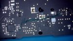
So I took a look at the ISL area, the entire area was pretty bad with the liquid damage. So I replaced several resistors that looked bad, as well as the ISL.
Tested again: same result
So now I actually had to pull out my multimeter and think ??
So I took voltage measurements around ISL, and would get some solid voltages on some lines. But most of them where pulsing on and off. (Also much higher voltages than a known good)
So after hitting my head, on the wall for an hour. I decided to take the iPhone approach. Diode measurements. So I took measurements of ISL and compared to known good. Pin 17 was way higher than a known good (560 instead of the 130)
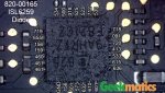
So I started following the schematic and ended at R7150. This resistor had the correct diode measurement ?so my next thought was, do I have continuity from pin 4 of R7150 and R7152. I did not. This was my issue. Somehow the trace between these two is broken (all pads and TP are okay)
So I ran a jumper from R7152 to U5600, and what do you know. Batteries charging.
Pretty much long story short: Diode mode for the Win. And this is why I decided to put out the DMs for the ISL chip.
As always: high quality pics available at:
 logiwiki.shinycomputers.com
820-00165 - it came for battery not charging, powers on with charged battery
When I disconnected the battery, I got fan spin for a second, then fan dying. Then fan spin for a second. On and on. (Not quarter fan spin)
So I check my PPBUS voltage. I got a constant loop of 9v to 0v.
So I took a look at the ISL area, the entire area was pretty bad with the liquid damage. So I replaced several resistors that looked bad, as well as the ISL.
Tested again: same result
So now I actually had to pull out my multimeter and think ??
So I took voltage measurements around ISL, and would get some solid voltages on some lines. But most of them where pulsing on and off. (Also much higher voltages than a known good)
So after hitting my head, on the wall for an hour. I decided to take the iPhone approach. Diode measurements. So I took measurements of ISL and compared to known good. Pin 17 was way higher than a known good (560 instead of the 130)
So I started following the schematic and ended at R7150. This resistor had the correct diode measurement ?so my next thought was, do I have continuity from pin 4 of R7150 and R7152. I did not. This was my issue. Somehow the trace between these two is broken (all pads and TP are okay)
So I ran a jumper from R7152 to U5600, and what do you know. Batteries charging.
Pretty much long story short: Diode mode for the Win. And this is why I decided to put out the DMs for the ISL chip.
As always: high quality pics available at:
MacBook Diode Mode Measurements - LogiWiki
We have Apple MacBook and iPhone Diode readings and general fault finding information compiled by the leaders in this area