KC Micro Tronix
Member
This one has me stumped.
PP3V42 is good and was measured at the CD3215's
The CD3215's appear operational and light up on thermal normally.
None of the rails appear shorted. (but we are not getting 20v at this point)
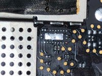
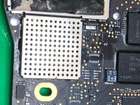
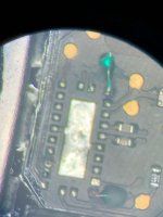
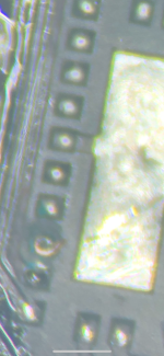
There was water damage on this board. Most all the damage was localized round U2890 I had to replace all the pull up 3.3K resistors that were tied to 3V3 TBT X Flash as well as the cap. I also pulled and inspected U2890 for pad damage and reflowed.
I am not getting 20v on the charger. I see some chitchat activity and can watch each CD3215 light up on thermal when I move from jack to jack. Current draw is almost 0. I have diode checked all around the TI CD3215 chips and compared against my reference board. Everything passes in diode test. I do not think there is a issue with either of the CD3215's and water was not present in this area.
I have read the data sheet on U2890 and don't see how a serial data storage device could be the cause of this.
I need to learn more about the CD3215's
If anyone has any input I would greatly appreciate it.
PP3V42 is good and was measured at the CD3215's
The CD3215's appear operational and light up on thermal normally.
None of the rails appear shorted. (but we are not getting 20v at this point)
There was water damage on this board. Most all the damage was localized round U2890 I had to replace all the pull up 3.3K resistors that were tied to 3V3 TBT X Flash as well as the cap. I also pulled and inspected U2890 for pad damage and reflowed.
I am not getting 20v on the charger. I see some chitchat activity and can watch each CD3215 light up on thermal when I move from jack to jack. Current draw is almost 0. I have diode checked all around the TI CD3215 chips and compared against my reference board. Everything passes in diode test. I do not think there is a issue with either of the CD3215's and water was not present in this area.
I have read the data sheet on U2890 and don't see how a serial data storage device could be the cause of this.
I need to learn more about the CD3215's
If anyone has any input I would greatly appreciate it.