820-01041-07 Stuck at 5.19V and 0.035A - PPBUS_G3H at 20mV - CHGR_EN_MVR unstable

stef4n

Member
Hello,

I'm working on a A1990 that does not turn on anymore. Charger is stuck at 5.19V (stable) on each of the 4 USB-C ports, power stays at 0.036A (+/-0.002A).

With the battery plugged in, logic board not taken out, I measured:
3.37V on the testpad PP3V3_G3H_RTC_X
7.59V to 12.27 on the PPBUS_G3H, unstable.

With the battery unplugged, logic board not taken out, I measured:
40 to 160mV on the testpad PP3V3_G3H_RTC_X
20mV for PPBUS_G3H measured on R3451, pin2
17mV for PPBUS_G3H measured on C3503, pin1
Then I checked CHGR_EN_MVR on R6968, pin1 and pin2. It reads a 200 to 400mV, fluctuating a lot. Might peaks very briefly at 1.x V, unless it's due to the autorange of the multimeter

There is no short on PPBUS_G3H; red probe on pin1 of C3503, black probe on a screw shows 0.7 MOhm

Given the ~20mV of CHGR_EN_MVR, the value of PP3V3_G3H_RTC_X is not a surprise.

Page 68 shows ISL9240 should give CHGR_EN_MVR, which, on page 67, enables PP3V3_G3H_RTC_X, whose value should be 3.38V.


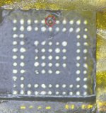
Currently taking the logic board out of the case to measure what the ISL9240 receives as inputs.


Background:
The defective logic board is in a MacBook that had its top case+keyboard+battery replaced at the Apple Store in May.
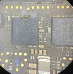
The logic board, in its current condition, could win a beauty contest.


Is there any way to make sure that the ISL 9240 is the culprit at 100% ?
I never had to unsolder such a chip so far. Wondering if I would be better off finding a rat lab to train myself before.
 
Last edited:

2informaticos

Administrator
Staff member
Getting EN_MVR will not help you, until you get PPBUS_G3H; it powers 3V3_G3H_RTC power supply.

Post U7000 basic voltages, with charger alone (no battery); P_IN, AUX_DET, SMC_RST_IN, VDDA/P, CBC_ON, A/BMON.
 

stef4n

Member
Hi,
Sorry for the delay in posting the missing voltages; the idiots at the apple store messed up with the screws heads holding the logic board, I had to find an iron bit to get rid off several heads with a driller -_-

Out of the case, with just one pair of Thunderbolt ports plugged on it, the ampmeter reads 5.17V at 0.172A.
(Yesterday in the top case it was 5.19V at 0.036A)

My PPBUS_G3H is at 0.00 mV measured on C6582, pin1

Regarding the U7000:
P_IN (PPDCIN_G3H_CHGR) : 0 mV (C7027 pin 1)
AUX_DET : 0mV (R7015 pin 2)
CHGR_RST_IN : 12.7mV
SMC_RST_IN :
VDDA: 110mV (test pad & R7075 pin1)
VDDP: 110mV (test pad)
CBC_ON: could not find a way to measure this one
A MON: 20mV (R5439 pin1)
B MON: 3mV (R5429)
_________

I plugged the charger cable into the other USB-C port, but part of the same pair. This time, the multimeter shows 5.17V, and it's fluctuating between 0.36 and 0.48A.
Moreover, I measured PPBUS_G3H again, on R4802, pin1, and it's cycling: 7.9V to 12.28V

________
I moved the same connector on the other side of the board. When plugged, one port shows 5.19V and 0.036A; the other one 5.14V and fluctuating between 0.36A and 0.48A
USB_C_XB_CC1_CONN, PPBUS_G3H on R3451 pin 2 shows a cycling PPBUS_G3H 7.9V to 12.28V
USB_C_XB_CC2_CONN, PPBUS_G3H on R3461 pin 2 shows 0.0V
(when charger plugged in the relevant USB-C port, obviously)

Did the same test with the other pair of USB-Connector; plugged into each side of the logic board;
1 port shows 5.17V and fluctuating Amps (0.36-0.48), with PPBUS_G3H cycling,
the second one is either stuck at 0.036A one one side, or at 0.172A the other side

R3452 and R3462 are good, 4.04 kOhms
R3451 and R3461 are good, 10.1kOhms
R3453 and R3463 are good, 5.00 kOhms

________
Measurements taken again on U7000, but this time with the charger plugged on the USB-C port at 5.13V (0.36-0.48A)
Regarding the U7000:
P_IN (PPDCIN_G3H_CHGR) : 5.10 V (C7027 pin 1)
AUX_DET : 120 to 300mV (R7015 pin 2)
TP_CHGR_SMC_RST_L : 37mV to 3.2V
CHGR_RST_IN : 0mV

VDDA: 5.16V (test pad & R7075 pin1)
VDDP: 5.14V (test pad)
CBC_ON: could not find a way to measure this one
A MON: 13 to 84mV (R5439 pin1)
B MON: 1mV (R5429)

Currently reading https://logi.wiki/index.php/CD3215_Bootup_Sequence
 
Last edited:

2informaticos

Administrator
Staff member
You must get same behavior on all USB-C ports.
If not, you have problems on USB-C areas.

Check and compare diode mode readings around CD3215 chips.
Start with their LDOs and CC1/2 lines.
 

stef4n

Member
Hi @2informaticos,

I did the measurements for U3100 and U3200, then when I saw the UB300 the cause of the issue became kind of obvious...

U3100U3200UB300UB400
{} = XA{} = XB{}=TA{}=TB
PP1V8_UPC_{}_LDOD0.445V0.445V0.009V0.446V
PP1V1_UPC_{}_LDO_BMC0.451V0.459V0.45V0.455V
PP3V3_UPC_{}_LDO0.41V0.406V0.009V0.41V
PP1V8_UPC_{}_LDOA0.478V0.48V0.477V0.48V
USBC_{}_CC10.535V0.539V0.5V0.537V
USBC_{}_CC20.535V0.54V0.000V0.473V

I missed it the first time I inspected the board; it was the single part of the Logic Board covered by a layer of dust.
 

Attachments

  • CD3215B300.jpg
    CD3215B300.jpg
    215.2 KB · Views: 3

stef4n

Member
I removed the UB300, cleaned the pad and reapplied solder, but the pad 91 seems gone. I can't re-apply solder on it. What's the best way to fix that?

I assume I will have to solder a tiny wire from pin 2 of DB529 to pin 91 of the new CD3215.

But pin42 of JB500 seems a bit more problematic...It seems there is a trace from Pin 2 of DB529 to pin42 of JB500 though. So, would a wire from "pad 91" of UB300 to pin 2 of DB529 be enough ?
 

Attachments

  • edited_image0.jpeg
    edited_image0.jpeg
    305.8 KB · Views: 3
Last edited:

2informaticos

Administrator
Staff member
There are 3 more USB ports to use.
I don't think someone really needs to connect the charger and 3 USB devices at same time.
And probably that port will also work when you flip the USB device connected.

If you want to fix it properly, check trace continuity and see which part need to rebuild.
 

stef4n

Member
I agree but ideally I'ld like to give back the device with 4 working USB-C port.
I blew away the ESD 8011 protection diodes DB504 and DB529:(
 
Last edited:

stef4n

Member
I replaced the burnt CD3215. I did not put back theDB504 and DB529.

I now have 5.19V and 0.4A on 2 USB-C port (1 on each side of the board), the 2 other are still stuck at 0.034A

New measurements for U3100 and U3200

U3100U3200UB300UB400
{} = XA{} = XB{}=TA{}=TB
PP1V8_UPC_{}_LDOD0.44V0.453V0.465V0.455V
PP1V1_UPC_{}_LDO_BMC0.458V0.466V0.72V0.463V
PP3V3_UPC_{}_LDO0.417V0.414V0.36V0.417V
PP1V8_UPC_{}_LDOA0.485V0.487V0.49V0.488V
USBC_{}_CC10.54V0.55V0.54V0.548V
USBC_{}_CC20.55V0.55V0.54V0.548V

I checked 3 times PP1V1_UPC_TA_LDO_BMC on UB300, I got 0.72V each time, seems a bit high.
And LDO at 0.36V a little bit low
 
Last edited:

2informaticos

Administrator
Staff member
Did you solder same termination code?
C00, A12, B03 are not compatible.

Did you compare again diode mode readings around the CD3215 chips?
Do you get correct LDOs voltage on all of them?
 

stef4n

Member
Did you solder same termination code?
C00, A12, B03 are not compatible.

Did you compare again diode mode readings around the CD3215 chips?
Do you get correct LDOs voltage on all of them?
Yes sir I did, CD3215C00Z,
Yes I did took new measurements around the CD3215, I was editing my post to include these measurement when you replied :)

LDO reading seems a bit high for PP1V1_UPC_{}_LDO_BMC and a bit low for PP3V3_UPC_{}_LDO
 

stef4n

Member
Yesterday evening, probably yes as I cleaned everything for a few minutes. Tonight, the measurement is the same: 0.72V
 
Last edited:

2informaticos

Administrator
Staff member
Then you have bad solders, or that chips is bad.

Please, don't quote an entire post, visible few centimeters above...
 

stef4n

Member
Sorry for the quote, i must have missclicked.
WIll redo the job this evening and let you know. Thanks.

Edit: CB304 is now out of the board,it looks like I perhaps broke it while trying to measure 1V1_LDO_BMC. Can't solder it back in place.
I measured it, 1.12uF. If I can measure it, I don't understand why I can't put it back in place.

Edit: I found a 820-1958 (MAcBook Air 2020) donor board, took the C2830, schematics shows 2.2uF, measured it, 0.3nF...going to pick them all one by one and test as I do not have any 2018 MacBook Pro donor board
Might be luckier if I pick one on the same part of the circuitry xD

Edit: C3206, 1.03uF, but 6.3V; C4423, 2.1uF, 4V
Looks like I ripped off the pad of CB304, will scratch the surface to solder on the trace

I replaced the CD3215;
UB300
{}=TA
PP1V8_UPC_{}_LDOD0.44V
PP1V1_UPC_{}_LDO_BMC0.455V
PP3V3_UPC_{}_LDO0.355V
PP1V8_UPC_{}_LDOA0.478V
USBC_{}_CC10.542V
USBC_{}_CC20.543V

1V1_UPC_TA_LDO_BMC is now in line. But, I still have to solder back a new CB304

I didn't succeed, but I plugged the power, and I still get 5.19V@0.03A on 1 port on each side, and 5V@0.36A on the other. That's less than before actually.
 

Attachments

  • CB304_resizedV2.jpg
    CB304_resizedV2.jpg
    423.3 KB · Views: 1
Last edited:
Top