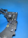
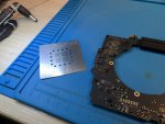
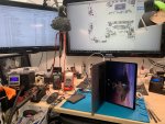
820-01949 LD at left side (dual CD3217 next to each other)

george-a

Member
Hi guys,

little water damage at CD3217 closest to the hall sensor on the side where there are 2x CD3217s together.

Cleaned and removed the chip to find out that 3rd ball from the top left (ball 48?) is short to ground (had to remove the other CD3217 to double check although I could also see corresponding the pull-up resistor - no short there).

This signal according to other schematics (820-01700) is TBT_T_CIO_PWR_EN and in 820-01949 is connected using a 10k resistor to 3.3V_LDO. Also in 820-01949 this signal seems to be independent for all CD3217s while in 820-01700 it is shared for each CD3217 pair and doesn't seem to have a pull-up to LDO.

I assume TBT_T_CIO_PWR_EN is the same pad for all CD3217s in all motherboards.

5V/0.275A at USB-C meter.

Any ideas?
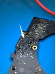
IMG_3377_2.JPG
 

2informaticos

Administrator
Staff member
"I assume TBT_T_CIO_PWR_EN is the same pad for all CD3217s in all motherboards."
This line comes from a GPIO pad, so is firmware dependant.
If the chips have the same marking code termination, shouldn't have any difference.
Possibly all the boards use the same pad for this function; can be confirmed 100% with schematic only.

To correctly identify the pads from your board, compare with other board which use the same CD3217 chip.
This way avoid any firmware dependency issue.
 

george-a

Member
I used 820-01700 as a reference exactly because it has CD3217s - I didn't know TBT_T_CIO_PWR_EN is firmware depended but I assumed its the same in all motherboards that use that chip.

Question is if this signal is shorted on one CD3217 does that mean that the PCH or something else on that line is toast? can you suggest other boards that have CD3217 so I could double (triple) check? What is the closest schematic for 820-01949?
 

george-a

Member
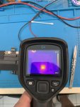
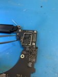
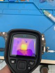
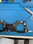
OK I used the thermal camera to detect the partial short of 0.09A of pad 48. It was the Intel Retimer JHL8040R (every CD3217 has one JHL8040R companion), and when removed the short cleared. I soldered back the second CD3217 (good one) I removed at the beginning to take comparison measurements and left out the LD CD3217 and of course the shorted Intel JHL8040R hoping that the board can start or reach 20V without thise. Unfortunately the board keeps going to 5V/0.280A and at this point with the thermal camera I also noticed the T2 gets a bit warm. Not sure if thats normal or T2 is toast and thus game over. See attached pics:

IMG_3492_2.jpgIMG_3493_2.jpgIMG_3494_2.jpgIMG_3495_2.jpg
 

george-a

Member
ok now that schematics are out the shorted signal (pad48) of U3100_X was I2C_UPC_X_INTM_L which routes to pad10 of U2800_X (intel tb retimer).. when I removed U2800 the short cleared but I see that this IC is on two data buses (as shown in pic) - could this lead to T2 damage? --there were no other liquid spots on the motherboard.

any other reasons T2 could give out some heat? ie performing some normal operation before we see 20V on charger?

u2800_x.png
 

2informaticos

Administrator
Staff member
A good communication is required between T2 and CD3215 chips, to allow 20V on input.
Did you test the board after removing U2800?
 

george-a

Member
yes I tested the board with same results -> 5V/0.280A

Ill replace U2800 and check again - waiting for parts.
 
Top