820-01958 Pulsing on PP1V8_SLPS2R

prodigy83

Member
Board is out
Board is stuck at 5v, it seems to draw amps .3 or less
I have pulsing on PP1V8_SLPS2R which I found when trying to inspect the boot up process of the CD3217 chip.
The board did have some significant liquid damage in the r3091 and top right of u3100.
When plugged in to power, my thermal cam shows the bottom left corner of the u7800 chip, then it looks like it shoots power (from the heat) to L7810.
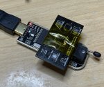
I have had to run jumper wires because of the significant liquid damage noted above.
Not finding any shorts.
 

prodigy83

Member
Also, how do I renew my membership upgrade? My CC expired and when i try to cancel my membership since there is no other option, it wont let me cancel the memberships since it says "Your membership may have been cancelled already."
 

prodigy83

Member
Meter never restarts, and is not stuck on .3 amps. When I first plug in the USB meter draws no amps, but after about 30-40 seconds, the amps jump to .39, for about 3 seconds, then the amps drop back to 0, and it repeats this cycle, the meter never reboots, but stays on 5v.
PPBUS_G3H goes from 12.3 to 11.3, so looks to be pulsing.
PP3V3_G3H_RTC is not pulsing at all. At a solid 3.2v

Just noticed Q7030 pin 1 and 8 is erratic pulsing all over.
 
Last edited:

2informaticos

Administrator
Staff member
Probably more components damaged by corrosion.
Did you change U3100?
Be sure all resistors from page 23 are good, as traces too.

Try reflashing U3060.
Don't forget to make backup first...
 

prodigy83

Member
I have swapped out both the U3100 and U3200 chips, no difference. These resistors are part of the problem. Let me upload a picture. The schematics I have do not show where all these circular pads are going to except for the closest one by C3011 at the top right of this cap. What do you mean by flashing U3060? Reflow? When I replaced U3200, to two capacitors (C3202 and C3102) now appears to be reading at 405 wheras before they were reading in the low 100's. I have jumper wires as you see running to the same circuits. Still no change. I am stumped.
lr-board-0001-1.jpg
 

2informaticos

Administrator
Staff member
You need USON-8 to DIP-8 adapter.
 
Last edited:

prodigy83

Member
Okay, I got the parts in today and I have been fussing with it all day long. I have used multiple software programmers but one of them told me the chip may be write protected and to click unprotect. I have tried this but get no where. It reads the chip just fine, but I cannot erase or reprogram the chip. What am I doing wrong?
 

Attachments

  • 2023-02-20_18-06-33_563-2.jpg
    2023-02-20_18-06-33_563-2.jpg
    168.6 KB · Views: 0

prodigy83

Member
Thanks, I used another chip from a donor board and I am having success, but I am trying to use the .bin file you provided but it tells me it successfully programmed the chip, but when I close out the program and reaqd the chip again, the chip goes back to what it had before. I also clicked verify and it is not matching up. See image below.Screenshot 2023-02-21 100450.png
 

prodigy83

Member
Well, 1/3 different programmers (software) worked I believe. I used the NeoProgrammer and even though it did not have the exact chip. I chose the one closest to W25Q80DV. Now to see if this helped.
 

prodigy83

Member
Now to see if this helped.
The board is now at 5v but never pulls amps until after about 30 or so seconds, but then the USB-C meter reboots at random with both sides. Could this be because of the programming issues I have had? I know usually if it reboots like this, the CD3217 chip may need to be reflowed/replaced. This was my first programming of the SPI chip so I am unfamiliar with this process.
 

2informaticos

Administrator
Staff member
You must be sure that TBT ROM was successfully programmed.

I suppose you have more damage caused by corrosion.
Severe liquid spill can affect T2, or CPU data lines.
 
Top