fodelement
New member
Hello!
I have always interested in component level repair, so when the opportunity to get a liquid damaged Mac Book Air arrived, I was delighted. So bear with me, as this is my first attempt at this.
I have a Green/Orange on the Mag Safe, but no fan spin.
Below are my voltages.
PPBUS G3H = 8.58
PPBUS_S5_HS_COMPUTING_ISN = 8.58
PPBUS_S5_HS_OTHER_ISNS = 8.58
PPDCIN_G3H_ISOL = 15.13
PPDCIN_G3 = 15.13
PP3V42_G3H = 3.44
PPVRTC_G3H = 3.33
PP5V_S5 = 5.2
PP5V_S4RS = 3.34 Pulse
PP5V_S0 = 3.14 pulse
PP3V3_S5 = 3.33
PP3V3_S4 = 0.33
PP3V3_SUS = 3
PP3V3_S3 = Pulse 2
PP3v3_S0 = Pulse 1
PP3V3_S4SW_SNS = Pulse 3
PP3V3_S0SW_SSD = 2.3
PP3V3_S4_TBTAPWR = Pulse 3
PP1V8_S3 = 1.7
PP1V2_S3 = Pulse .70
PP1V05_SUS = 1.06
PP1V5_S0 = 1.5
PP0V6_S0_DDRVTT = Pulse .34
PP1V05_S0SW_PCH_HSIO = 1.05
PP5V_S4RS3 = Pulse 3.34
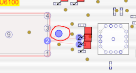
The little corrosion I found was near U6100. I cleaned with with isopropyl alcohol. I measured all 16 terminator resistors and they are fine. The only issue I can find (besides the voltages) is Pin 2 on U6100 (SPI_MLB_MISO), does not have continuity with R6114, R6123 or it’s VIA (824). My questions are…
PS: PS:32 > IS:24 > Wagner 08")
I have always interested in component level repair, so when the opportunity to get a liquid damaged Mac Book Air arrived, I was delighted. So bear with me, as this is my first attempt at this.
I have a Green/Orange on the Mag Safe, but no fan spin.
Below are my voltages.
PPBUS G3H = 8.58
PPBUS_S5_HS_COMPUTING_ISN = 8.58
PPBUS_S5_HS_OTHER_ISNS = 8.58
PPDCIN_G3H_ISOL = 15.13
PPDCIN_G3 = 15.13
PP3V42_G3H = 3.44
PPVRTC_G3H = 3.33
PP5V_S5 = 5.2
PP5V_S4RS = 3.34 Pulse
PP5V_S0 = 3.14 pulse
PP3V3_S5 = 3.33
PP3V3_S4 = 0.33
PP3V3_SUS = 3
PP3V3_S3 = Pulse 2
PP3v3_S0 = Pulse 1
PP3V3_S4SW_SNS = Pulse 3
PP3V3_S0SW_SSD = 2.3
PP3V3_S4_TBTAPWR = Pulse 3
PP1V8_S3 = 1.7
PP1V2_S3 = Pulse .70
PP1V05_SUS = 1.06
PP1V5_S0 = 1.5
PP0V6_S0_DDRVTT = Pulse .34
PP1V05_S0SW_PCH_HSIO = 1.05
PP5V_S4RS3 = Pulse 3.34
The little corrosion I found was near U6100. I cleaned with with isopropyl alcohol. I measured all 16 terminator resistors and they are fine. The only issue I can find (besides the voltages) is Pin 2 on U6100 (SPI_MLB_MISO), does not have continuity with R6114, R6123 or it’s VIA (824). My questions are…
- Should I be getting continuity from those locations? If so, is re-soldering the chip/replacing is my next step? I know it’s a BIOS chip, so it’s not a simple rip and replace.
- Is 15.13 too far out of tolerance for PPDCIN_G3H_ISOL/PPDCIN_G3 which should be 18.5?
- If I understood Louis's Rossmann Repair Training Guide correctly, should all of the rails be pulsing?
- Any other suggestions as to what I should look into?
PS: PS:32 > IS:24 > Wagner 08