820-4924-A - Doesn't turn on - Magsafe Orange

gluton

New member
Hello,
I'm trying to fix a motherboard who doesn't turn on from an 2015 macbook pro 13"" 820-4924-A.
No trace of corrosion at all.
When I plug the charger, the magsafe light start from orange for half a sec then turn green then turn to Orange.
I did SMC Bypass: the light on the magsafe start orange and turn green when I release the power button. It turn back orange when I press again power.
Nothing on the screen, no fan spinning.
I'm using an 60w apple official charger.

I took some measurement :

PPBUS_G3H : 12.55V
PP5V_S5
: 4.99V
pp3v42_G3H
: 3.42V
PP3V3_S4
: 0v
PP5V_S4
: 0V
PP3V3_s0
- 0.08V

I've been looking for PM_SLP_XXX :

PM_SLP_S0_L : 3.33V
PM_SLP_S3_L
: Pulse few ms once when the charger is plugged in then go to 0v
PM_SLP_S4_L
: Pulse few ms once when the charger is plugged in then go to 0v
PM_SLP_S5_L
: Pulse few ms once when the charger is plugged in then go to 0v
PM_SLP_SUS_L
: 3.33V

I look on internet and see that I need 11+1 prerequisites to turn on PM_SLP_S5_L, PM_SLP_S4_L and PM_SLP_S3_L to enable S4, S3 and S0 state power rails.

1. PPVRTC_G3H : 3.33v
2. RTC_RESET_L : 3.26v
3. PCH_SRTCRST_L : 3.26v
4. PCH_INTVRMEN(?_L?) : 2.51v
5. PCH_DSWVRMEN(?_L?) : 2.51v
6. SYSCLK_CLK32K_RTCX1 - Can't measure it because I don't have oscilloscope
7. PP3V3_S5 : 3.33v
8. PM_DSW_PWRGD : 3.42v
9. PP3V3_SUS : 3.33V
10. PM_BATLOW_L : 3.30v
11. PM_RSMRST_L : 3.03v
+1. PM_PWRBTN_L : 3.41V and stable

From what I understand from this post, PCH_INTVRMEN is coming directly from the PCH so it's :
- the PCH who is bad
- connection from the PCH to the PCB who is bad
- "series resistances"
Is that correct and if yes, which "series resistances" is it ?

Additional measurement :
pch_intruder_l : 1.67v (seem bad too)

Best regards
 
Last edited:

2informaticos

Administrator
Staff member
First of all, welcome to the forum!

"From what I understand from this post, PCH_INTVRMEN is coming directly from the PCH so it's"
Wrong understood; that is a PCH input.

"pch_intruder_l : 1.67v"
Is the only bad reading; it is also PCH input.
And PCH will not start power on sequence untill get the correct level.
Force it with 100K instead of 1M in place of R1301.
 

gluton

New member
When I trigger SMC_ONOFF_L, PM_PWRBTN_L drop at 0.32V and come back to 3.42 after release.
Sometime, PM_PWRBTN_L Stay at 0.32V until I cut the power.
 

gluton

New member
Other information :
When plug in the charger in
PP3V3_S4 pulse at 0.6V then go to 0V
PP3V3_S0 pulse at 0.7V(sometime 2.41V) then go to 0.07V
PP3V3_S3 pulse at 0.7V then go to 0.07V
 
Last edited:

2informaticos

Administrator
Staff member
You should note the pulse at PM_SLP_Sx_L signals at same time with drop pulse on PM_PWRBTN_L.
Be sure PM_RSMRST_L is always/steady high.
 

gluton

New member
Values when charger is plugged :
PM_RSMRST_L is at 3.03V and is stable
PM_PWRBTN_L : 3.42v
PM_SLP_S5_L
is at 0v
PM_SLP_S4_L
is at 0v
PM_SLP_S3_L
is at 0v
PM_SLP_S0_L
is at 3.34v

When I trigger SMC_ONOFF_L :
PM_RSMRST_L is at 3.03V and is stable
PM_SLP_S5_L
pulse to 1.5v then go back to 0v
PM_SLP_S4_L pulse to 1.41v then go back to 0v
PM_SLP_S3_L pulse to 1.31v then go back to 0v
PM_SLP_S0_L is at 3.34v and is stable
PM_PWRBTN_L
drop at 0.32V and go back to 3.42v

I Just realized that using my multimeter to check pulse could be not enough fast to catch accurate pulse value in this scenario. Unfortunately I don't have other measurement tools at my disposition ...
 
Last edited:

2informaticos

Administrator
Staff member
If you trigger SMC_ONOFF_L repedeatlly, may catch higher value.
However, 1.5V pulse can't be catched if respective signal doesn't pulse; good enough as confirmation.
You should check for pulse now on each power rail according with PM_SLP_Sx_L used as enable.

Try first to start in SMC bypass mode.
 

gluton

New member
I tried to start in SMC_bypass mode, but my fan will not speed at all (should turn at full speed from what I understood) and 0V on PM_SLP_SX_L.

These are the highest values I caught by trigger SMC_ONOFF_L repedeatlly :
ALL_SYS_PWRGD pulse at 2v
DDRREG_EN
: pulse at 2.37v
PM_SLP_S4_BTMUX_
L : pulse at 2.43v
PM_SLP_S3_BUF_L
: pulse at 1.41v
P1V05S0_EN
: pulse at 1.53v
P1V8S3_EN
: pulse at 2.34v
P3V3S0_EN
: pulse at 1.52v
P3V3S3_EN
: pulse at 2.34v
P5VS0_EN
: pulse at 2.31v
P5VS3_EN_RC
: pulse at 1.08v
PP1V05_S0
: pulse at 0.7v
PP1V5_S0
: pulse at 1.04v
PP1V2_S3
: pulse at 0.6v
PP1V8_S3
: pulse at 1.35v
PP3V3_S0
: pulse at 2.3v then go to 0.07v stable.
PP3V3_S3 : pulse at 2.01v then go to 0.07v stable.
PP5V_S0 : pulse at 3.72v
PP5V_S3
: pulse at 5v
S4_PWR_EN
: pulse at 2.35v
S5_PWR_EN
: 3.42V stable
USB_PWR_EN
: pulse at 1.23v
 
Last edited:

2informaticos

Administrator
Staff member
Check for pulse at pins 7 & 3 of U1950.
Be sure no corrosion present on its area.

Any pulse at L7630 and L7310/20?

You can also test the board removing Q8150.
 

gluton

New member
U1950 :
no visible corrosion
Pin 7 : pulse at 2.40v
Pin 3
: pulse at 1.10v

L7630 :
Pin 1
(P1V05S0_LL) : pulse at 1.2v
Pin 2
(PP1V05S0_REG_R) : no pulse

L7310 :
Pin 1
: no pulse
Pin 2 no pulse

L7320 :
Pin 1
: no pulse
Pin 2 no pulse

I removed Q8150 but I can't notice any change on the measurement
 
Last edited:

2informaticos

Administrator
Staff member
As per schematic, L7310/20 are tied together (on output pin); no need to measure both of them.
Also keep in mind, DC voltage must be checked on output pin; no reason to check both pins of a coil.

Really strange to get pulse on pin 3/U1950 but not on L7310/20 (VCORE).
Use quality flux and heat PCH die area.
No more than 200 degrees, for 15-20s; no need to melt the balls, just burn eventually accumulated crap.
PCH_INTRUDER_L issue denotes a problem on that area.
 

2informaticos

Administrator
Staff member
Tie together pins 5/6 of U1950 and test again the board.
Also check for pulse at PLT_RESET_L.

Can you note pulse on all output voltages from page 63?
Check them for short to ground.
 

gluton

New member
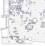
I made mistake and my ground probe touched some part of the motherboard and burnt something.
I don't know what exactly burnt, but the short came from that location just like the smell.
Couldn't find anything burnt with my eyes.
mb.jpg

The logic board is doing pulse by itself every 4 sec.
I can hear a little tick coming from Q7180, Y1915, Y1905, Y5110
I have no more drop pulse on PM_PWRBTN_L when I trigger SMC_ONOFF_L
SMC_ONOFF_L
doesn't make any measurements I took before pulse anymore but still affect the led of the magsafe when maintain close when the charger is plugged, the led doesn't change of color.

PM_SLP_S0_L : 0.07V and pulse at 2.3v (was at 3.33v stable before)
PCH_PM_SLP_S0_L : 3.33v stable
PP3V3_S0 : 0.07v pulse at 2.3v
PM_SLP_SUS_L : 3.33V
SMC_PM_G2_EN : 3.33v

ppvrtc : 3.33 stable
rtc_reset_l : 3.26 stable
PCH_srtcrst_l : 3.26v stable
PCH_intvrmen : 2.51v stable
PCH_DSWVRMEN : 2.51v
PP3V3_S5 : 3.33v
PM_DSW_PWRGD : 3.42v
PP3V3_SUS : 3.33v
PM_BATLOW_L : 3.30v
PM_RSMRST_L : 3.03v
PM_PWRBTN_L : 3.41v and stable
pch_intruder_l : 3.0v

PM_PCH_SYS_PWROK : 0v pulse at 1.50v

PM_SLP_S0_L, from what I understand, it's coming from U1420.
PCH_PM_SLP_S0_L go to pin 1-2 of U1420.
U1420 is powered by PP3V3_S0_PCH_GPIO
and should output PM_SLP_S0_L

o_O
 

2informaticos

Administrator
Staff member
I don't understand anything from that picture.
I can't see any location marked there.

Don't bother with PM_SLP_S0_L.
In fact, I don't understand how did you get 3V there (first post), if this signal is pulled up to 3V3_S0.
As per schematic, U1420 avoid high level on this signal, if machine isn't in S0 state.
 
Top