
-
For $29/mo, we provide access to advanced level technicians who will answer your questions on any Macbook board related matter to the best of their knowledge promptly & walk you through how to solve your problem so you can deliver a working board to your customer.Subscribe Now
You are using an out of date browser. It may not display this or other websites correctly.
You should upgrade or use an alternative browser.
You should upgrade or use an alternative browser.
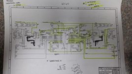
A1502 820-3476 No S4 - I'm lost
- Thread starter Tony Tone
- Start date
Tony Tone
Member
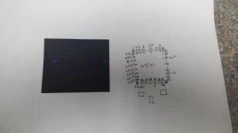
Duke. Awesome. Nice to meet you. I only have a piece of shit analog oscilloscope. I was seeing Louis's video on 1/4 spin earlier, LOL. The R1300's and whole region are good (visually) and get 3.3V. I'm getting 2 paralel lines on the oscilloscope and they look like they are moving pretty fast (like the curve of a lowercase f). Think I need a digital one? I can order one right now. & dead on 5V_S4.
& I am going to look into what these areas are about too. Thank you for some direction : )
& I am going to look into what these areas are about too. Thank you for some direction : )
Last edited:
Tony Tone
Member
Wow. You guys are dedicated to assisting. Thank you. & thank you for some direction. I'll order my digital oscilloscope bc it seems important. Thought this analog would be good enough. & I'll look closer to what you guys are pointing at and report back : )
Not trying to have you guys fix it, I gotta do my part too. Don't want to waste your time.
Thank you.
Not trying to have you guys fix it, I gotta do my part too. Don't want to waste your time.
Thank you.
Last edited:
Tony Tone
Member
My assumptions that I am at least seeing something on the 1960's silly scope is good enough to assume its functioning properly being more practical is a good one.
Thank you. I think the area I did work on around the U1900 is not good enough. I'm going to recheck it. U1845 looks bad around there. I'm waiting on an appointment at local recycler to find a donor board, don't trust whats online bc they look pretty janky. Thanks. I'll follow up with my results.
Thank you. I think the area I did work on around the U1900 is not good enough. I'm going to recheck it. U1845 looks bad around there. I'm waiting on an appointment at local recycler to find a donor board, don't trust whats online bc they look pretty janky. Thanks. I'll follow up with my results.