Hello there,
I have a A2141 MacBook Pro with board 820-01700-A that doesn't power on.
I had recently reinstalled the operating system. Then out of nowhere it didn't want to turn on anymore.
I don't have much knowledge repairing mac boards other than placing one test lead on ground and the other one on each component, and replacing them, etc. I don't know if this is the proper way on testing caps and other coils on mac logic boards.
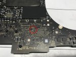
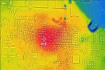
Now, long story short, I placed the board under my thermal camera to locate the short or the fail. But I cannot visualize the component with the short since almost immediately the heat circle covers about ten components at the same time.
So I decided to measure one by one. So I seted my multimeter to check for continuity on all heat circulated components shown on my thermal imager.
They are all capacitors, but they all emit continuity on both sides when testing them. Does this mean they are all shorted?
Then I changed from continuity measurement to diode measurement, and each capacitor measures 10v but in the diagram the measurement is: 20UF 20% 2.5V X6S-CERM 0402 C782
I will appreciate suggestions and tips on how overcome this problem.
Best regards
I have a A2141 MacBook Pro with board 820-01700-A that doesn't power on.
I had recently reinstalled the operating system. Then out of nowhere it didn't want to turn on anymore.
I don't have much knowledge repairing mac boards other than placing one test lead on ground and the other one on each component, and replacing them, etc. I don't know if this is the proper way on testing caps and other coils on mac logic boards.
Now, long story short, I placed the board under my thermal camera to locate the short or the fail. But I cannot visualize the component with the short since almost immediately the heat circle covers about ten components at the same time.
So I decided to measure one by one. So I seted my multimeter to check for continuity on all heat circulated components shown on my thermal imager.
They are all capacitors, but they all emit continuity on both sides when testing them. Does this mean they are all shorted?
Then I changed from continuity measurement to diode measurement, and each capacitor measures 10v but in the diagram the measurement is: 20UF 20% 2.5V X6S-CERM 0402 C782
I will appreciate suggestions and tips on how overcome this problem.
Best regards