
Hi. This is my first post. I am studying troubleshooting for motherboard. I would like to learn something from all of you. Thank you.
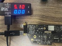
I have an 820-02016 that won't power on. The USB-C voltage is around 5V and it's consuming almost 0A of current. There's a clicking sound coming from the motherboard.
PPBUS_ANON → 12.33V
(FP800-1)
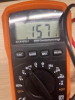
PP3V8_AON_VDDMAIN → The voltage is unstable(approximately 5 to 10V)
(C5887-1)
I’m not sure what to do for the next troubleshooting step, any suggestions are welcome. Thank you.
I have an 820-02016 that won't power on. The USB-C voltage is around 5V and it's consuming almost 0A of current. There's a clicking sound coming from the motherboard.
PPBUS_ANON → 12.33V
(FP800-1)
PP3V8_AON_VDDMAIN → The voltage is unstable(approximately 5 to 10V)
(C5887-1)
I’m not sure what to do for the next troubleshooting step, any suggestions are welcome. Thank you.


 ️U8800