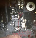
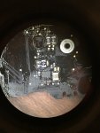
Corrosion everywhere on 820-00165

Yustina

New member
Got a macbook that had nasty corrosion and build up all over, not knowing better I threw it in the ultrasonic and now I am able to see the damage. My first questions are:
1: am I supposed to have U7190 as a chip or just soldered pads on the board? (I know this might be a dumb question but I have been researching this board and all the pics I have found have the area where that component goes looking like a ghost town, with only solder pads and no components (chips, resistors nor capacitors) )

2: I am missing some of the gold check points on the board (not sure what these would be called) that as per boardview, these appear to be related to a power grid, what are the do's and dont's when running jumping wires? Since these are pads on the board itself and form part of a circuit of about 5 components. I will provide more details once I am back in my garage.
thx in advance!
 

Alan.L

Member
1. These are no stuff pads. It said on the schematic as "NO STUFF"
2. Gold check points are "Test point" and yes sometime boardview often have more test points than on actual board.
 

Yustina

New member
Thanx for your reply! Ok, so no worries there on the "no stuff" areas, I was not sure about what it meant, now I know. As for the test points, these are gone from corrosion, not missing, didnt explain my self there. They are more so dark deep spots and I am thinking I need jump wires but not sure.
 

dukefawks

Administrator
If the test points are "in line" and break a trace then they should be fixed of course. Some test points are also on top of a via, so those suck to fix.
This board doesn't sound very fixable, can you post some HiRes pictures of it to see if this thing is worth fixing?
 

Yustina

New member
Its a mess and a hell of a project for my learning but really a great challenge ! I will post some pics once Im home.... the "holes" where the test points were are not in line with any component nor on any path that I can see, just at the sides of a diode (will post which one) that is part of PP3V42, per the schematic, these test points should measure 3.42V. Again, I will post hi res pics once I get back home.
Thx so much!!
 

Yustina

New member
Here are the pics of the area of the board where the test points are gone (i apologize for the quality, cant find my camera), the diode in the middle is D7005. Overall the board looks fine, didnt find any traces messed up nor anything, with the exception of these test point that I thought were needed to complete the circuit but, as I am posting this, I am realizing they are called TEST POINTS only so, not really needed for functionality correct? Of course like you stated, unless they were on a trace line or on top of a via. One of these ALMOST ate a via away. (i think) You_Doodle_2017-05-17T23_55_30Z.jpgIMG_0098.JPG
 

Yustina

New member
There is no voltage present, i get no green light in the charger, I have not spent too much time with this board so have not troubleshot too much, I just basically needed to know if those test points by that diode were A MUST and if they were, what jumpers I needed to run, but they are not needed then, correct?
 

dukefawks

Administrator
Do some measurements around D7005 and see if power is getting to U7090. Check 3V42 rail for short. But if the whole board looks like this area then it is probably trash.
 

Yustina

New member
today I plugged this board in to start measuring some grids and U0500 started smoking =(
the smaller glass portion is actually cracked and cracked some more when plugged in, Im thinking this is for the bin now huh?
 
Top