Macbook Pro a2159 820-01598 - Not Turning on, stuck at 5v

edgetarian

New member
Greetings, I just wanted to preface this by saying I'm quite novice when it comes to motherboard repair and have been cutting my teeth with this board for the past week or so.

I work in an I.T. department and fixes like this are outside of our scope usually so I don't have any assistance with trying to solve my issue.

Essentially, the Macbook is not starting up, black screen, unable to enter DFU (keyboard method, haven't tried switch method yet since 1v25 source is on the rear side of the board).

No water damage apparent.

I've tested a few voltages that make me think its an SMC related issue. My few readings are:

PPBUS_G3H = 12.26V
PP3V3_G3H = 0V
PP3V3_G3H_RTC = 3.3V
PP1V8_SLPS2R = 0V
PPDCIN_G3H_CHGR = 4.95V

Sorry if this readings are nonsensical or sporadic, I just wanted to try and streamline my learning by getting some pointers from those with much more knowledge and experience than myself.

Any recommendations, suggestions, etc would be greatly appreciated.

Thanks.
 
Last edited:

2informaticos

Administrator
Staff member
First of all, welcome to the forum!

"PP1V8_SLPS2R = 0V"
Impossible to access DFU mode in such case.
Check diode mode to ground there.
 

edgetarian

New member
Thanks for the quick response! Glad to learn that I didn't waste my time trying to solder jumpers for manual DFU access.

Just got back in the office, doing a diode mode to ground test netted in a reading of 0.000.
 

edgetarian

New member
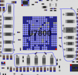
Check diode mode on other coils around U7800.
Just asking for a mild clarification, when you say coils, are those inductors?

I'm assuming I should be checking the L78... series coils, but I just wanted to make sure because they are under some kind of metal shield. (If you have any pointers for removing this I'd also appreciate it because I'm having a hard time finding out if it's soldered to the board or just clipped in).

Sorry for my general ignorance. I've also attached an image with the coils I'm talking about for reference.

Thanks again for your help.
 

Attachments

  • coils to check..PNG
    coils to check..PNG
    98.4 KB · Views: 2

2informaticos

Administrator
Staff member
You have lot of available capacitors connected to these coils; check the opposite board side.
Did you think to use them as test points?
 

edgetarian

New member
You have lot of available capacitors connected to these coils; check the opposite board side.
Did you think to use them as test points?
Appreciate the insight, I was definitely overthinking that.

I took some diode readings and here are my results:

L7810 (PPVDDCPUSRAM_AWAKE)
  • 0.390
L7811-L7812 (PP0V82_SLPDDR)
  • 0.000
L7809-L7808-L7807-L7806 (PPVDDCPU_AWAKE)
  • 0.000
L7813 (PP1V8_SLPS2R)
  • 0.000
L7814-L7815 (PP1V1_SLPS2R)
  • 0.322
L7816-L7817 (PP0V9_SLPDDR)
  • 0.000
L7819-L7820 (PPVPCORE_S5)
  • 0.190
L7821-L7822 (PP1V_PRIM)
  • 0.118
L7823 (PP0V9_SSD0)
  • 0.285
L7824 (PPVCCQ_ANI_SSD0)
  • 0.346

Best regards
 

2informaticos

Administrator
Staff member
Did you check removing charger and battery?
If yes, then you have pure short (0 ohm) on varioue lines.
That can be caused by T2, or U7800 itself; almost impossible to have shorted caps on 3 different power rails.

BTW, any reason to quote an entire post visible few centimeters above?
Write into bottom reply box, instead of clicking Reply button.
Please, maintain forum aesthetic...
 

edgetarian

New member
My bad.

Yes I took the diode readings without power from charger or batteries.

I was doing the readings on test pads, should I have been on caps instead? Pardon my ignorance again...

If it is either T2 or U7800, is there some way I can narrow it down to one or the other? Do people often change U7800?

Thanks as usual.
 
Top