
-
For $29/mo, we provide access to advanced level technicians who will answer your questions on any Macbook board related matter to the best of their knowledge promptly & walk you through how to solve your problem so you can deliver a working board to your customer.Subscribe Now
You are using an out of date browser. It may not display this or other websites correctly.
You should upgrade or use an alternative browser.
You should upgrade or use an alternative browser.
[SOLVED]820-00165 - No 3.3V on Pin1 of SPI-ROM
- Thread starter bjf
- Start date
- Status
- Not open for further replies.
bjf
Member
No Title
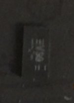
Ok, so pin 1 on the SPI ROM is open - no reading in diode mode. ROM is removed. Pin 1 has continuity to U6101. I've replaced U6101. I'm not exactly sure of the orientation of the U6101 chips I just got in the mail. I'm attaching a picture. I'm assuming the bottom right is pin 1. No dot, just a line. Any thoughts?
Ok, so pin 1 on the SPI ROM is open - no reading in diode mode. ROM is removed. Pin 1 has continuity to U6101. I've replaced U6101. I'm not exactly sure of the orientation of the U6101 chips I just got in the mail. I'm attaching a picture. I'm assuming the bottom right is pin 1. No dot, just a line. Any thoughts?
Attachments
Get a scrap board so you can also compare measurements and take the correct chip from the donor. I'm pretty sure pin 1 should have something on diode mode with red to GND. All pins must measure something at least. I have no scrap 00165 to compare here right now to be 100% sure. Just order a pile of scrap boards, you will need them anyway.
bjf
Member
Yeah, I compared it to a another 00165 and it's supposed to be around .590 with U6101 present and ROM removed. It's open with U6101 and ROM removed. I've used up all of my U6101 chips from donor boards. That chip is only on 2015 Air and Retina boards so they went fast which is why I bought a large quantity of new ones. Just wasn't sure of the orientation but I have it now (opposite of my pic.)
So, the results: No change after installing newly purchased U6101. And no change after installing known-good ROM and factory U6101 from other 00165 board. It still gets 0V on pin1 of ROM and around 1.1V on SPI_MLB_CS_L / SPI_SMC_CS_L. Also, I've confirmed that SPI_MLB_CS_L / SPI_SMC_CS_L will measure 3.3V on a good board with no ROM or U6101 installed.
So, the results: No change after installing newly purchased U6101. And no change after installing known-good ROM and factory U6101 from other 00165 board. It still gets 0V on pin1 of ROM and around 1.1V on SPI_MLB_CS_L / SPI_SMC_CS_L. Also, I've confirmed that SPI_MLB_CS_L / SPI_SMC_CS_L will measure 3.3V on a good board with no ROM or U6101 installed.
Last edited:
bjf
Member
Sorry, I left that out of the results above. The measurements on this ROM are normal now (.590 on pin 1) with the known-good U6101 installed correctly. I had the open result because I had U6101 reversed. As far as the ROM swap, it's only for testing. No intention of leaving them that way. To be sure of things, I tested this boards ROM and U6101 on my known-good board and it powers up normally.
So the problem is with SPI_MLB_CS_L / SPI_SMC_CS_L not hitting 3.3V. It's at around 1.1V. It looks SPI_SMC_CS_L comes from the SMC. Diode measurements on that line are at .615 versus .515 on a good board.
So the problem is with SPI_MLB_CS_L / SPI_SMC_CS_L not hitting 3.3V. It's at around 1.1V. It looks SPI_SMC_CS_L comes from the SMC. Diode measurements on that line are at .615 versus .515 on a good board.
- Status
- Not open for further replies.