vaeel91
New member
Hello everybody, i hope you can help me with this problem, im getting mad.
So the issue started when the display cable was disconnected with the device powered, after that, total black screen. (I tried 2 different screen working known)
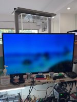
The screen is total black, no backlight and no image at all (I've tried pointing a torch to check if there is any image, there is not, i also have 28/30v on the backlight routes)
Connecting the mac to external monitor will show the recovery sometimes, sometimes grey screen (maybe the type-c hdmi adapter im using is not fully compatbile) but still, i get some image on the external monitor.
I've tried running some measurements on the display FPC, first of all, all the voltages are present (with display connected and device powered on)
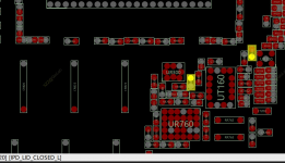
The only route going directly into the cpu is DISP_BKLT_LSYNC and i get a diode value about 340 wich is good for me.
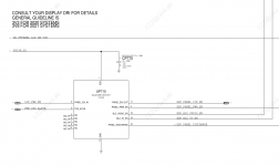
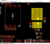
And there i begin to feel lost : in the boardview there is a IC called "UR000" alias Larkspur, in the schematic i think its the " UP701 "it have a pin under it called "EDP_PANEL_1V8_EN", i think this is a propretary chip, cuz there is no information about it, even searching the code on the chip on google gives 0 results.
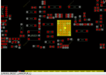
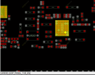
Do you know what this line exactly do ? it is possible that this line is critical to wake up the display ?
Do you have any ideas what is causing black screen? im not very experiences on macbooks, but its strange to me that all voltages are present and still no image
So the issue started when the display cable was disconnected with the device powered, after that, total black screen. (I tried 2 different screen working known)
The screen is total black, no backlight and no image at all (I've tried pointing a torch to check if there is any image, there is not, i also have 28/30v on the backlight routes)
Connecting the mac to external monitor will show the recovery sometimes, sometimes grey screen (maybe the type-c hdmi adapter im using is not fully compatbile) but still, i get some image on the external monitor.
I've tried running some measurements on the display FPC, first of all, all the voltages are present (with display connected and device powered on)
The only route going directly into the cpu is DISP_BKLT_LSYNC and i get a diode value about 340 wich is good for me.
And there i begin to feel lost : in the boardview there is a IC called "UR000" alias Larkspur, in the schematic i think its the " UP701 "it have a pin under it called "EDP_PANEL_1V8_EN", i think this is a propretary chip, cuz there is no information about it, even searching the code on the chip on google gives 0 results.


Do you know what this line exactly do ? it is possible that this line is critical to wake up the display ?
Do you have any ideas what is causing black screen? im not very experiences on macbooks, but its strange to me that all voltages are present and still no image

