A2338 M1 Macbook Pro 13" - Internal display not working but outputs to External display (DFU restore/revive Failed)

GoliathX0X0

New member
EDITED: Hello! I’m new to this forum — and I did something pretty stupid.

I picked up a used top case and an aftermarket display, then swapped over the logic board and Touch ID. Everything worked fine until what I did next.

I got a popup to “complete the service,” so I tried to finish the pairing process, but it failed. I assumed the aftermarket display was the issue, so I tried again — but in the process I disconnected the eDP cable. Since then, the internal screen hasn’t worked at all: no image, no backlight, and also no camera/light sensor. I tried the original damaged screen and no luck. It does still output to an external display.

EDITED TO ADD: There are no signs of liquid or physical damage at all on the board.

I attempted a DFU restore/revive, but it failed, and now it won’t boot into macOS. It does boot into Recovery on an external display.

Here’s what I have available right now:

  1. Hot air station + iron
  2. Binocular microscope
  3. Multimeter + other tools
  4. Board schematic
  5. Decent soldering experience and understanding of electronics
I dont have an oscilloscope or a bench power supply.
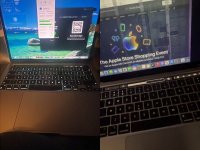
I have done some research and some forums are pointing to RD560. Before I prod at it. I would greatly appreciate help to repair this MacBook. I have attached images of the laptop with the screen working and the following diagnostic screens I came across.

Thank you,
G
collage (1).jpg
 
Last edited:

2informaticos

Administrator
Staff member
First of all, welcome to the forum!

Did you touch video connector without disconnecting charger and battery?
Is your board 820-02020 model?

Check diode mode to ground on JP600 lines and compare with good board, or reference table.
Also check if UP710 has correct outputs signals (4, 11, 14).
 

GoliathX0X0

New member
Hi, thanks for the warm welcome and thank you for your response.
I did indeed disconnect the cable when it was powered on with the battery connected. I feel extremely stupid about this.

I do think it is a 820 - 02020. It’s a 2020 M1 MacBook Pro 13 16/256GB
EDITED: confirmed it is a 820 -02020 A based on the silk screen on the board

I don’t have another board to compare with but now you have given me the table to compare with I shall take a closer look.

Sorry this might be a stupid question when you said check the lines, do you mean to ground with each point on the board that is connected with the part?
EDITED: Do I do it with power in the board or without?

I did glance through the beginners guide - if you could direct me as to where to go that would be great.
Again, I would like to thank you alot. You have given me great advice so far.
 
Last edited:

2informaticos

Administrator
Staff member
Allow 10-15s once power is removed (charger & battery), before checking in diode mode, or ohm scale.


GoliathX0X0

New member
First of all, welcome to the forum!

Did you touch video connector without disconnecting charger and battery?
Is your board 820-02020 model?

Check diode mode to ground on JP600 lines and compare with good board, or reference table.
Also check if UP710 has correct outputs signals (4, 11, 14).
Hi upon testing JP600 with components connected I observed the following:
EXPECTED/TheoreticalTESTED
JP600_PIN_10Defaultd0.3320.34
JP600_PIN_12Defaultd0.3310.339
JP600_PIN_14Defaultd0.3650.365
JP600_PIN_16Defaultd0.3680.364
JP600_PIN_18Defaultd0.0010 (possibly too low for my meter)
JP600_PIN_2Defaultd0.6070.614
JP600_PIN_20Defaultd0.6430.657
JP600_PIN_22Defaultd0.6430.657
JP600_PIN_28Defaultd0.0010 (likely meter precision error)
JP600_PIN_30Defaultd0.5960.58 (but 0 at RP663 - No component present)

EXPECTED/TheoreticalTESTED
JP600_PIN_32Defaultd0.5951.51(Will re confirm) HIGH
JP600_PIN_34Defaultd0.5951.52 HIGH
JP600_PIN_36Defaultd0.5871.52 HIGH
JP600_PIN_38Defaultd0.0010
JP600_PIN_40DefaultdOLOL
JP600_PIN_42DefaultdOLOL (through RP673)
JP600_PIN_8Defaultd0.0010 (likely meter precision)
 
Last edited:

GoliathX0X0

New member
At UP710
@4 - 0.549
@11 - 1.156 (red to ground - 0.556)
@14 - (unable to check as test point is underneath up700 - Please confirm if i am to remove component)
thanks again i appreciate it.
 
Last edited:

GoliathX0X0

New member
JP600_PIN_32Defaultd0.595Red to ground: 0.581
JP600_PIN_34Defaultd0.595Red to ground 0.583
JP600_PIN_36Defaultd0.587Red to ground 0.583

Just updating as i get the expected values by testing by polarity (as per instructions red to ground - black to component)
 

2informaticos

Administrator
Staff member
Really important pins to check are 2, 4, 6, 24, 26, 45, 46.

Pins 8, 18, 28, 38 are connected to ground; through RP674-7.
No reason to check GND to GND in diode mode, nor ohm scale.
If good in diode mode, then check their voltage.

"check if UP710 has correct outputs signals (4, 11, 14)"
I expected voltages there, with machine turned on.
 

GoliathX0X0

New member
Thank you for your response. will check the pins 2, 4, 6, 24, 26, 45, 46 in diode mode aswell.
For pins 8,18,28 and 38 and pins 4,11,14 i check for voltages with it turned on as in plugged in with the power button pressed?
If possible please tell me if the expected values as listed above are within reason, as in they are good and i can proceed with more testing.
Thank you again.
Pins 8, 18, 28, 38 are connected to ground; through RP674-7.
No reason to check GND to GND in diode mode, nor ohm scale.
If good in diode mode, then check their voltage.

"check if UP710 has correct outputs signals (4, 11, 14)"
I expected voltages there, with machine turned on.
 

2informaticos

Administrator
Staff member
Why would you want to check in diode mode (to ground) the pins connected to ground?

"For pins 8,18,28 and 38 and pins ... 11 ... i check for voltages"
What voltage do you expect on grounded pins???
Put some logic on your job.

Your readings look close enough to expected values in diode mode.
Apart of pins 40 & 42, where "OL" is expected; 0 (short to ground) is not same as open line...
Is RP673 connected on your board?
 

GoliathX0X0

New member
Why would you want to check in diode mode (to ground) the pins connected to ground?

"For pins 8,18,28 and 38 and pins ... 11 ... i check for voltages"
What voltage do you expect on grounded pins???
Put some logic on your job.

Your readings look close enough to expected values in diode mode.
Apart of pins 40 & 42, where "OL" is expected; 0 (short to ground) is not same as open line...
Is RP673 connected on your board?
For grounded pins - it should be 0V - i understand your point.
About earlier, i understand my question was a little stupid as I actually misread what you wrote - the way I work is methodical. Even if I know the expected output I have the tendency to confirm it anyways. Since I don’t run a repair shop and because this is a personal laptop I try to go word by word in-terms of the instructions given to me.
I will be getting needle tips for the probes as I dont have them - with this I think I might be able to measure the pin 14 of UP710. The tips I have are too big. I see that I should have gotten an open loop but it gave me a short as bridged the contacts by accident when measuring.
RP673 does not exist on my board - my apologies I should have specified that I tested the point as per the schematic.
I will retest all values and confirm.
Just out of curiousity how do i measure pin 2 on UP700 for 1UP710? I see 4 pins on each side - on the schematic i only see 6. So if its pin 2, i count as per the schematic its next to pp5v_s2 to the left. Are the pins not labled - so for example pin 4 is not listed. would that be a blank to the left of pin 3 (also pp5v s2)?
Thank you for your patience,
gScreenshot 2026-02-08 143832 (2).pngScreenshot 2026-02-08 143832 (2).png
 
Last edited:

2informaticos

Administrator
Staff member
Use the name of the line and find proper test point.
If no other component with easy access is connected, try to identify the line and scratch a bit on it.

In this case, just check UP701/10 outputs.
If you get correct voltages, then enable pins are correctly driven.
When you check voltages image & backlight related, internal LCD must be connected.

BTW, write directly into bottom reply box, instead of clicking Reply button.
I don't see any reason to quote an entire post, visible few centimeters above.
Please maintain forum aesthetic...
 

GoliathX0X0

New member
Thank you for your response. I will do the needful and update you.
As for responding - I see two buttons. One reply directly to the recent update by you. And another by the box where you type. This would be confusing to any new user on your forum. It is not with the intent to quote an entire post/make the forum look disorganized. Going forward I will reply from the box itself.
Thanks for understanding.
 

GoliathX0X0

New member
Hello again,
update: With the screen connected and power via cable,
up710 pin14 is also accessible through via tb462. - I got 1.78 to 1.8 V

up710 pin 4 at ta277 - i got 1.8V

up710 pin 11 i got about 1.79V

These are two vias that werent on the schematic i have - as in connected to the POI.
am i on the right path?
 
Last edited:

2informaticos

Administrator
Staff member
OK, then 3V3/5V_SW_LCD should be present too.
You can check them on the filter capacitors.

Now check LPPD_INT_HPD voltage; RP611 is a good test point.
 

2informaticos

Administrator
Staff member
This signal comes from T-CON board.
CPU can't recognize internal display.
You should try known good LCD assembly.

Be aware, do NOT connect Intel screen; A2159, or A1706/8 screens can kill the CPU.
 

GoliathX0X0

New member
Thank you for the advice - I have two screens. One known good - brand new screen aftermarket (which worked up perfectly until I did what I did) and one OEM screen which had lines showing up on the screen - still partially functional even if i fully cant see everything.
Both of these screens worked. Now both do not get an image.
I will not attempt to connect the wrong display. Thank you for warning me.
As of now do you suggest I still buy another screen to test? (for context here are the screens both for the a2338)
 

Attachments

  • collage (2).jpg
    collage (2).jpg
    325.2 KB · Views: 0
Last edited:
Top