
Hi there,
I need your advice on troubleshooting the cause of failure The purpose is to get the data from the Macbook. The MacBook was very dusty. Here are the symptoms and measurements.
Macbook On Battery / Without Batter Connection --> all 4 USB-C ports shows the same --> 5.15v 30 mAmps - just stable, no jumps.
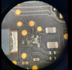
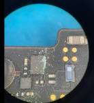
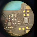
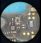
Removed the Board and it was dusty, cleaning with high-pressure air without damaging component but did not applies any isopropyl to check it under the microscope. While observing the board, saw that U5620 has greenish corrosion on the right side of it. I see damage near pins 2 and 3 of U5620.
Then I observed greenish corrosion on R9012, R9010, and C9002. See the attached picture. Cleaned the area using Isopropyl alcohol. Please check the attached pictures.
Information about some Power Lines:
PP5V_S4_T_USBC - 0v
PPDCIN_TA_G3H_F - 5.1v
PPVBUS_USBC_TA - 0v -
PP3V3_G3H_RTC_X - 0v (primary power for CD3217 missing)
PPBUS_HS_3V3G3HRTC_X - 0v
PPBUS_G3H - 0v (we need to check the Charger Chip - U7000)
PPDCIN_G3H - 5.1v
F7000 - 0v on pin_1
F7001 - 0v on pin_1
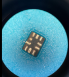
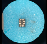
I am again lost. Now I removed the U5620 and did measurements and waiting for your advice. Thank you.
regards,
Zeyd
I need your advice on troubleshooting the cause of failure The purpose is to get the data from the Macbook. The MacBook was very dusty. Here are the symptoms and measurements.
Macbook On Battery / Without Batter Connection --> all 4 USB-C ports shows the same --> 5.15v 30 mAmps - just stable, no jumps.
Removed the Board and it was dusty, cleaning with high-pressure air without damaging component but did not applies any isopropyl to check it under the microscope. While observing the board, saw that U5620 has greenish corrosion on the right side of it. I see damage near pins 2 and 3 of U5620.
Then I observed greenish corrosion on R9012, R9010, and C9002. See the attached picture. Cleaned the area using Isopropyl alcohol. Please check the attached pictures.
Information about some Power Lines:
PP5V_S4_T_USBC - 0v
PPDCIN_TA_G3H_F - 5.1v
PPVBUS_USBC_TA - 0v -
PP3V3_G3H_RTC_X - 0v (primary power for CD3217 missing)
PPBUS_HS_3V3G3HRTC_X - 0v
PPBUS_G3H - 0v (we need to check the Charger Chip - U7000)
PPDCIN_G3H - 5.1v
F7000 - 0v on pin_1
F7001 - 0v on pin_1
I am again lost. Now I removed the U5620 and did measurements and waiting for your advice. Thank you.
regards,
Zeyd
Attachments
-
 R9012, R9010 and C9002 chips.png788.8 KB · Views: 0
 -
 U5620 chip after cleaning.png787.7 KB · Views: 0
 -
 U5620 chip and damage on it..png802.7 KB · Views: 0
 -
 U5620 Corrosion.png695.5 KB · Views: 0
 -
 U5620 removed and place on board.png869.2 KB · Views: 0
 -
 U5620 removed and place on board_2.png842.4 KB · Views: 0

