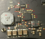
Iv got an 820-00138-A in for repair, it has image but no backlight. Have tried another screen but still nothing. Its a difficult one as no boardview for it, so a nightmare to try and work out what is what. I have made the following diode readings, but don't have another board to compare it to so not overly sure what is correct and what isnt. I can see there are a couple of OL's in there. Im not sure if they should be or not, as the boardview that is marked as the 820-00138-A doesnt actually resemble the 820-00138-A .
v noticed pin 3 of q7706 is OL, its LCDBKLT_EN_L . I have tried it pos to ground and neg to ground in diode mode, and both show OL. Not sure if this is correct or not ?
PPVOUT_S0_LCDBKLT at the connector is 0.00 at the fuse its 12.55
If I check continuity between the connector pin and the diode / caps its showing as 000.3 so it appears to be connected ok to the connector.
PPBUS_SW_LCDBKLT_PWR @ q7706 = 12.55v
LCDBKLT_EN_L @ q7706 = 12.44v
PPVOUT_S0_LCDBKLT @ connector = 0.00v
PPBUS_S0_LCDBKLT_PWR_SW = 0.15v
BKLT_EN_R = 3.3v

