820-00840 / No boot / PP3V3_G3H Short to ground

2informaticos

Administrator
Staff member
Check USB-C connector terminals for corrosion first.
Next, compare diode mode readings on CC1/2 lines with the other port.

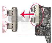
USB data lines are referred with BOT (bottom) and TOP (top) in their name.
Compare similar TOP and BOT lines, in diode mode to ground.
 

Papaille

Member
Ok thanks.
No corrosion at all.

USBC_XA_CC1 (Bottom-U3100 linked one) : 0.745
USBC_XA_CC1_CONN : 0.868
USBC_XA_CC2 (Top-U3100 linked one) : 0.751
USBC_XB_CC2_CONN : 0.866
USBC_XB_CC1 (Bottom-U3200 linked one) : 0.749
USBC_XB_CC1_CONN : 0.860
USBC_XB_CC2 (Top-U3200 linked one) : 0.763
USBC_XB_CC2_CONN : 0.881

Found that the faulty one is the Bottom port-U3100 linked, the only one with a different value on one UsbC connector pin (see picture below)

I have a pin that's not Open Lined, but with 0.040 in diode mode. In this page (http://logi.wiki/index.php/USB-C_Pinout), i suppose it's the D+

Also remembered a thing :
When i have plugged yesterday my charger+usb-c meter on the faulty usb-c port (before knowing it was partially ko) got 20v and 0.7 amp but i see a tiny flashlight and a "pop" sound near U3100, on the left side of the chip (around C3109). It doesn't change anything on the Usb-c meter, and board continue to run fine. Maybe a blowing capacitor?
 

Attachments

  • Capture d’écran 2021-11-18 à 12.10.16.png
    Capture d’écran 2021-11-18 à 12.10.16.png
    629.1 KB · Views: 0
Last edited:

Papaille

Member
Ok. I made a mistake, CC1 lines are top, CC2 bottom (regarding to schematic)
So supposed faulty line is USBC_XA_USB_TOP_P, witch is equal to USBC_XA_USB_DBG_TOP_P

On schematic, there is only one component on this line, D3312. This is that you call TVS diode?

Only TVS Diodes called like this on schematic are D3308/D3309/D3408/D3409, that's why i ask this. (and all seems to be goods, diode mode done before on CC1/2 lines are fines)

To test D3312, i need to remove the shield covering all connector and U2800. Never done that before, so i want to be sure not doing a mistake again...

Lastly, can i remove D3312, checking diode mode, and if it's open line, plug directly my charger on this port? No major risk doing this?

Thanks
 

2informaticos

Administrator
Staff member
If there is pure short, you can use voltage injection method.
Start with 1V and increase bit a bit, if needed.
 

Papaille

Member
Hum… i see.
So if I resume, it’s a data line partially shorted.
It Could be U3100, D3312 or replaced redriver chip, nothing more on the line.

two options: continue investigating, or just use the machine like that.
Is there a risk to use it with this short? (I mean plug-in a device and burn it)
And is there a configuration in thunderbolt 3 that use both side of connector at same time? (I suppose for high speed data/power or something that could be limitate the machine usage in time) or it’s just a side that doesn’t work and that’s all?

thank again
 

2informaticos

Administrator
Staff member
Only one side of USB-C port is used at a time.
You can test fi that low value disappears removing USB redriver chip.
 

Papaille

Member
Thanks for suggestion!
So i removed redriver chip, low value still here (little bit high but still there)

I decided to test the board without redriver, and all sides of all connectors works. So then i decided to solder a "new" Redriver chip (from my 5 units lot) with a different method (making solder bulb on the chip, not on the board) and slowly heating the board. Redriver is now soldered on the board, and all sides are working!

I try to remove maximum flux, but i don't have ultrasonic cleaner. My flux is this one : https://www.computer-systems.gr/en/content/product/cs-flux-10g
Is there a risk to leave it on the board?

I can't test thunderbolt link for the moment (only have charger usb-c interface) but will test it later.
 

Papaille

Member
That's what i did (isopropyl+toothbrush), but still have sticky flux on the board, unable to remove it only with toothbrush and isopropyl. Don't want to use pcb cleaner, already have a bad experience with it.
 

Papaille

Member
Ok thanks.

So i tried the board on dual screen and usb-c dock.

On first usb-c connector (U3200 link) no screen detected, but all things connected in usb-c (ethernet / USB / charger) is ok, in both sides
On second usb-c connector (U3100 link) i have the output for the screen, and the video recopy is ok. But i have major detection problems with docks (ethernet is ok, but didn't charge a phone or other issues, in both sides)

In my system preferences, when a monitor is plugged even in first or second connector, nothing appears in the thunderbolt area (no connection detected) but it seems to works fine on the second connector...

Don't know if it's interesting to investigate more, but it's a little bit frustating....
 

2informaticos

Administrator
Staff member
USB redriver chip should be involved on these symptoms.
May also have some broken trace on the Thunderbolt area.
 

Papaille

Member
Should I remove the redriver chip and see if it run better without? This chip is my major problem on this board, and is involved in all my issues since the beginning… assuming it’s not a Perfect way to leave the board without it, but with it it’s worse…

Thunderbolt area looks fine.
 

Papaille

Member
For sure. But each chip is for a single port, no communication between them for theses lines, right?
supposing I soldered a partially bad u3200 (u3100 is still the original) data line can make all my usb-c equipments to work but didn’t’ detect a monitor ?
 

2informaticos

Administrator
Staff member
HDMI output is managed by U2800, which can be affected on some of its USB data lines.
If USB redriver chip was burnt, is because of overvoltage, usually from fake charger; sometimes even PCH dies.
 
Top