820-00850 stays at 5v

Hello everyone!

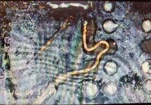
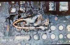
Have this board, the story behind says that it felt down while hdmi was pluget and since then, no power. The board was first taking 0v on left side and 5v 0.3amp on the right side ports. After opening up and inspecting, i saw that on the left side usb c cable was actually not plugged in and the connector on motherboard was damaged and i presume it was damaged in previous shop and not by the impact it self (they screwed the metallic clamp on top still). I tried to fix the connector(it was a bit bend) and plugged it back, got 5v on this side as well.

However i didn't like how the connector was looking i removed in to be sure there is no shorts in it.. still 5v on the other side..

My understandings is that there is one of CD chips that is blown witch affect the whole system there fore i have multiple questions:

Best way to get this chip? If its from a donner board then it does need reball? How to get the old chip out (compound around it).

And also regarding the connector, is it possible to use from a donor board or must be new? My understanding is that it will have to be soldered on using hot air since no access to pins, how then i should menage it in sort to be sure everything is soldered right and also not melt it?

Edit: Forgot to check PP3V3_G3H, will do that tomorrow, but have a feeling its not related to charger ic..

Thank you!
 
Last edited:

2informaticos

Administrator
Staff member
MLB shoud have broken traces/solders, after the impact.
The glued CD3215 chips are not easy to remove; be very carefull there!

If you are not sure about resoldering another USB connector, leave it working with one side only; avoid to generate more damage on the board.

Like any T2 board, PPBUS_G3H must appear before 3V3_G3H.
Do you get 5V at R7020?
 
The right side where the headphone connector is, will check latter witch UB it is
Tried to replace isl9240 from a donor board, not sure if i did it correctly, but the behavior didn't change
 
Sorry, was in a rush i guess :/ any suggestions on what to check next?
By the way, i was able to harvest usb c connector from a donor boards, will try to install it. It does not have a direction, right?

And the one thats still one the board is ub300/400

Edit: The connector is on board and i get 5v on this side as well how ever i noticed that the amp are a litlle different

Its at 5.21v and 0.4amp on the UB100/200 and at 5.21v and 0.16amp on the UB300/400

Not sure if it make any differences
 
Last edited:

2informaticos

Administrator
Staff member
"UB100/200"
Do you mean U3100/200?
Seems to have a problem on that area, with 400mA.

Check F3000/1, as FB200/1 too.
Post voltage and diode mode to ground on LDO lines of all CD3215 chips.
Be aware, 1V1 LDO (LDO_BMC) should appear only on the powered port.
 
Yes, UB3100/200

By the way, i just did some more research and it appear that in my understandings PPBUS_G3H is created by U7000, thats why i replaced it.

Okay i will take mesurments and post back.

Thank you!
 

2informaticos

Administrator
Staff member
"PPBUS_G3H is created by U7000, thats why i replaced it."
Even if it doesn't get R7020 voltage???
Put some logic on your work!

BTW, there doesn't exist any UB3100, nor UB3200.
 
Sorry, miss spelled it, its U3100/U3200
All 4 fuses are ok

U3100
PP1V8_UPC_XB_LDOD = 1.795
PP1V1_UPC_XB_LDO_BMC = 1.116
PP3V3_UPC_XB_LDO = 3.350
PP1V8_UPC_XB_LDOA = 1.813

U3200
PP1V8_UPC_XB_LDOD = 1.796
PP1V1_UPC_XB_LDO_BMC = 1.118
PP3V3_UPC_XB_LDO = 3.355
PP1V8_UPC_XB_LDOA = 1.804

UB300
PP1V8_UPC_XB_LDOD = 1.815
PP1V1_UPC_XB_LDO_BMC = 0v
PP3V3_UPC_XB_LDO = 3.216
PP1V8_UPC_XB_LDOA = 0

UB400
PP1V8_UPC_XB_LDOD = 0v
PP1V1_UPC_XB_LDO_BMC = 0v
PP3V3_UPC_XB_LDO = 0v
PP1V8_UPC_XB_LDOA = 0v

There is something heating up around UB300/400, no metter in witch port the charger is plugged, will check it up

And apparently only one port is taking 0.16 amp and 3 others do take 0.40amp


Edit: measurement at CB308 appears to be only 20ohms. Will try to remove and see if it goes away

Edit 2: after removing CB308 the resistance is still at 20ohm and still getting warm.

Bad cd3215?

Diode mode on that line 0.012v...
Others chips 0.481
 
Last edited:

2informaticos

Administrator
Staff member
Very likely bad CD3215 chip.
But UB090 and CB090 are connected there too.

Check diode mode to ground on UB400 LDO lines too.
Compare readings with U3100/200.
 
Oh i see

Can the CD3215 cause the issue with PPBUS_G3H? And most likely its not UB090/CB090 since the CD3215 itself gets hot (no meter in what port i will plug the charger)

If i manage to remove it, will the machine start with out it?

Also will it be possible to use a replacement from a donor board? Is there any ways to reball it with out the stencil?
 

2informaticos

Administrator
Staff member
Donor chip can be used; new ones from China, not always good (fake, or reballed junk).
Correct stencil and solder paste is the easiest way.
You can also place the balls at hand on its pads and heat carefully, until get them soldered; not recommended way, too dificil.

T2 will try to talk with all CD3215 chips.
However, U7000 should generate PPBUS_G3H, once R7020 get 5V.
 
Thank you @2informaticos!

I am trying to find a replacement cd3215, but apparently its avalable only from china :/ i have donor board with them, but i unfortunatly dont have balls (its 0.3mm?) or stencil.. i gues there is no way around with out balls/stencil with paste?

Do you think my problem of not having 5v on R7020 is related to the short on cd3215 or there is actually two issues?
 
I tried to remove the glued usb c chip, how ever i damaged a couple of traces under... will this fix work?
Also there is no more heat coming from that area and the port now take only 0.24amps instead of 0.4amp

I suppose to receive the new chip next week, and hopefully it will work after that..
 

Attachments

  • 20211016_170827.jpg
    20211016_170827.jpg
    313 KB · Views: 0
  • 20211016_171340.jpg
    20211016_171340.jpg
    188.6 KB · Views: 0
Top