820-00850 Wont boot.

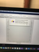
I have a 820-00850 board that came in and was not turning on. When I tested it, it would boot up to 20v 700ma for only about 15-20 seconds and the fans wound spin at normal speed for about 2 seconds then stop. Nothing on the screen. Then the board would seem to turn itself off and go to 20v 0.03a. The board looks very clean, but I did find some small corrosion in the CB565 and QB660 areas. The pad for pin 1 of CB565 was burnt and destroyed so I have left that off the board. I cleaned the corrosion and replaced a few caps and resistors around QB650. I also replaced QB651, QB660, and QB QB650. Was still getting the same result after this so I tried a T2 firmware restore but that failed and now the board will only boot to 5v 0.07a unless I do another T2 firmware restore. I did notice during the firmware restore, the board goes back to 20v 700ma for a few seconds and the fan spins for a second or 2 again, but then I get an error in apple configurator and the board now only shows 20v 250ma and the fans spin at full speed. I have attached a screenshot of the error. The board will only stay like this for about 2-3 minutes and then the fans turn off and the amps drop to 0.03. If you unplug the charger and plug it back in, it will only go to 5v 0.06a now. The rest of the board looks spotless so not sure where else to look. I took some measurements while the board was using 700ma and it appears to have all voltages including CPU voltage. Also took measurements while the board was using only 250ma and high fan spin and it looks like its only in S3 state. Any help would be appreciated.

20v 700ma20v 250ma
PP1V8_S3
1.8v​
1.8v​
PP1V8_S3_MEM
1.8v​
1.8v​
PP1V_S3
1v​
1v​
PP1V2_S3
1.2v​
1.2v​
PPVCC_S0_CPU
0.95v​
0v​
PPVCCSA_S0_CPU
1v​
0v​
PPVCCGT_S0_CPU
0v​
0v​
PPVCCEDRAM_S0_CPU
0v​
0v​
PPVCCIO_S0_CPU
0.95v​
0v​
PP1V2_S0SW
1.2v​
0v​
PM_SLP_S3_L
3.3v​
0v​
PM_SLP_S0_L
1.8v​
0v​
 

Attachments

  • image0.jpeg
    image0.jpeg
    659.1 KB · Views: 11

2informaticos

Administrator
Staff member
Do you get 0V9/1V8_SSD0 when board tries to boot?

There should be something more affected by liquid on the board.
 
Yes I do get 0V9/1V8_SSD0 when the board uses 700ma. I took the board out of the case and checked for any signs of liquid damage but the whole board looks perfect, except for the area around UB000. None of the liquid damage indicators were tripped on this one, so the spill seems to have been small. Not sure if maybe liquid under UB000 would cause this issue or not.

When I put the board back in the case just now and plugged in the charger, it now goes to 20v 700ma without me having to do a T2 firmware restore. It will only stay at 700ma for about 30 seconds or so before the amps drop to around 90ma and then after another 15 seconds or so, it tries to turn on again, then turns off. It keeps looping like that with no image on the screen, no USB activity and no caps lock reaction when the board is using 700ma.
 
I changed UB000 but still was getting the same error in apple configurator. I can get the board in DFU mode without issues, but the restore fails. Now I just tried it again and it failed with a different error that I have not seen before and now the board will only go to 20v 0.06a on charger. PP1V8_G3S, PP3V3_G3S, and PP5V_G3S are all up, but PP1V8_S5 and PP3V3_S5 are 0v. I also notice now that when the battery is connected, the board will only go to 19v 0.01a and if I connect it to another macbook to try another T2 restore, it will continuously loop from 5v, to 20v, and then off. I now cannot get the board into DFU with the battery connected because of this looping, but I tried it without the battery and it fails and the board only goes up to about 19v 0.18a and only one fan spins high. The other fan does not spin at all. Any idea what to check next?
 
Well I re-balled the original UB000 and put it back on but nothing seems to change. All 4 USB ports have the same behavior. I figured out the issue with the battery was the black insulation around the battery screw was missing and I was screwing the battery screw right on top of that. I guess the metal on metal contact was shorting something. I put some electrical tape there and screwed it down and now the board charges the battery when the charger is connected but wont boot still. I get 19v 2.22a with the charger and battery connected but no voltage on any S5 rails or higher. PM_SLP_S5_L is 0v but I seem to have all G3S rails. I tried another T2 firmware restore but I always get error 4010 "Device added from invalid state Restoring". During the restore process, both fans will spin at low speed for about 2 seconds and then stop and then about 15 seconds after that, the error comes up and now only the right fan spins at high speed, while the left fan does not spin at all. I am not sure where to go from here.
 

2informaticos

Administrator
Staff member
But you've got even CPU VCORE before; what happened?
Something else affected by corrosion reacted at heat...
 
I have started working on this one again. I took another look over the board an found that PP0V9_TBT_T_SVR was short to ground. I removed UB000 again and the short was gone, so the original UB000 was in fact bad and shorting that rail to ground. I have replaced it with another one from a 820-01041 board, since I do not have a donor for this model and the schematic says they are the same chip. I tried T2 restore again but it failed with the same error about invalid state. I then noticed the pins on U7100 looked at little corroded so I removed the chip, cleaned the pads and re-soldered it to the board and tried the T2 restore again and now it gets up to 700-800ma during the restore process for about 30 seconds and then it gives me an error and the amps drop to 70ma. The error this time is the same that I was getting originally, Error 9. Not sure where to go from here. Here are some voltages I measured on all the big coils and some other SSD rails, while the board was taking 700ma. The one that seems wrong to me PP2V7_NAND_SSD0 at 2.5v.

CHRG_LX1 - 12.56v
PP3V3_G3H - 3.35v
PP5V_G3S - 5.12v
PVCCEDRAM_S0_REG_R - 0v
PPVCCGT_CPU_PH3 - 0v
PPVCCGT_CPU_PH2 - 0v
PPVCCGT_CPU_PH1 - 0v
PPVCC_CPU_PH1 - 0.915v
PPVCC_CPU_PH2 - 0.949v
PPVCCSA_CPU_R - 1.012v
PP0V95_S0_CPUVCCIO_REG_R - 0.953v
PP1V2_S3_REG_R - 1.2v
PPVIN_S0SW_LCDBKLT - 0v
P5VUSBC_T_R - 0v
P5VUSBC_X_R - 0v
PP0V9_SSD0 - 0.901v
PP1V8_SSD0 - 1.797v
PP2V7_NAND_SSD0 - 2.51v
ALL_SYS_PWRGD - 1.8v
 
Yea finding a donor board for this model is not easy. I resorted to purchasing another broken A1989 on ebay that supposedly did not power on, to use for parts. Turns out this macbook I bought for parts actually works and is fully functional, so I was not going to start removing UB000 from this. I finally found another one that was cheap and this time is actually broken and cannot be fixed. I took UB000 off of this parts board and put it on this board I am working on. I then did another T2 firmware restore and this time I did not get any error, but it comes up with a padlock icon in AC2 and the computer still will not boot. The T2 firmware restore seems to have worked though because it now take 20v 0.580a steady. The fans spin and CPU have voltage but no USB activity or caps lock reaction. PLT_RST_L is 1.8v. Is there something else I can check on this one?
 
Top