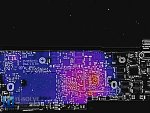
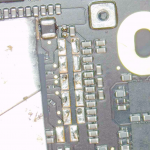
820-01521-02 - 5V 0.43A - No liquid damage - U7800 warms up

it-solve

Member
Tried DFU mode but did not get picked up.

Under IR U7800 seems to warm up to 34*C
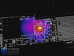
2022-02-01 21-16-38.JPG2022-02-01 21-17-36.JPG

No visible shorts on coils, low impedance on
P0V9SLPDDR_SW0 - 53Ohm
P0V9SLPDDR_SW1 - 53Ohm

While
P1V1SLPS2R_SW0 - 8.9kOhm
P1V1SLPS2R_SW1 - 11kOhm

Lifted up L7186/Lt187 low impedance seems to be on the PP0V9_SLPDDR side. Is that normal?

Where else shall I look?
 
Last edited:

it-solve

Member
P0V9SLPDDR_SW0 - 1.56V
P0V9SLPDDR_SW1 - 1.55V
PWDDCPUAWAKE_SW1/3 - 0.75V
others fine


Only these I am not getting on U8100 coils
CPUCore - 0V
P1VPRIM - 0V
P0V9SSD_SW0 - 0V
P1V8SSD_SW0 - 0V

All on the right side of u8100
IT-Solve_Repair_22-02-02_07-59-40.jpg
 

2informaticos

Administrator
Staff member
Don't check for DC voltage at "SW" side of a coil.
Always test the output pin (DC side), where the filter cap is placed.
If you use an o-scope, will probably understand the difference.

Check if all AWAKE and SLPS2R voltages are present.
 

it-solve

Member
So we should measure after the coil on outputs, rather than on the output pin side instead?

1643763006701.png


PP1V8_SLPS2R - 1.8V
PP1V1_SLPS2R - 1.1V
PP0V8_SLPS2R - 0V
Let me know if I missed any


P0V9SSD_SW0 and PP0V9_SLPDDR seem to get 1.6V now. After I unsoldered and soldered back L7816/7 not sure if related. Isn't 1.6V a bit too high for a 0.9V line?
 
Last edited:

2informaticos

Administrator
Staff member
I said do NOT check DC voltage on "SW" side of coil.
What is L7823 pin 1 voltage and pin2 of L7816/17?
These are the output pins for mentioned coils.

"PP0V8_SLPS2R - 0V"
This is a "good" reason for non working board.
Check diode mode to ground there.

Also check AWAKE voltages from the same page.
 

it-solve

Member
Roger that. Strange that all test points are placed there. Must be for o-scope.

L7823 - 0V - 0.373
L7816/17 - 1.57V

PP0V8_SLPS2R - 0.79V - 0.2389 - I must have mismeasured it.

PPVDDCPU_AWAKE - 0.75V
PPVDDCPUSRAM_AWAKE - 0.80V
PP1V8_AWAKE - 1.8V


All the remaining reported voltages are the same.
 
Last edited:

it-solve

Member
Just got functioning A1932 and referenced core diode mode readings on these 0V lines

PVCC_PRIM_CORE - 0.074 - 0.308 on a functioning board
PP1V_PRIM - 0.092 - 0.26
PP0V9_SSD - 0.064 - 0.276

Blown CPU / SSD? Not much dusty, used for high school classes mainly.
 

2informaticos

Administrator
Staff member
You can try changing U7800.

Once you've got working board on hands, write down diode mode readings on all coils, including the big ones.
This way build a boards library, which will save you time in the future.
 

it-solve

Member
Haven't replaced one of these 338S00267 -A0's before. Seems like Stencils and chips are available. Has anyone had success in replacing these?


it-solve

Member
Just for confirmation, I have lifted up all coils on these lines and seems like short is not on the side of the PMIC

1643796541464.png

PPVCC_PRIM_CORE - 0.0169
PP1V_PRIM - 0.0254
PP0V9_SSD - 0.35

Could that PMIC is fine unless PVCC_PRIM_CORE, inputs of it are blown (AE/F 18/19)?
1643796496976.png
 

it-solve

Member
bugger.

I saw some of them on sale with a touch id. Is touch ID serialized with the board? Can't it be reused?
 
Top