820-01949 stuck on 5V after liquid

Dozer

Member
3 of the 4 tb ports working "normaly, but stuck on 5v
1 the front left side starting the amp meter all time again

i found liquid problem under R3107 Pin 2, there was a big number in diode mode
I scratched the mainboard there and found a via. so i soldered a new resistor and a jumper wire to pin 48 U3100 and the via
now in diode mode is 0.566, should be ok

but still this port starts the amp meter all time from the beginning, all other ports ok but stuck on 5V

i replaced noe the u3100, no all ports normaly working but all stuck on 5 V and 400mA

PP3V3_G3H is 3.3V
PPBUS_G3H is 12.26V

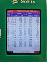
I checked all connectoins on J3300_CXT, the mac USB c meter shows ok as well

DZ3300_CXT and DZ3303_CXT I had a the feeling that they are not so nice and i pulled them out but no change without them

need some help please
 

Attachments

  • 20230316_163143.jpg
    20230316_163143.jpg
    266.8 KB · Views: 2

Dozer

Member
found here a hint

checked R3108/09 and found under R3109 pin2 korosion. will change and report back
 

Dozer

Member
no idea...

PPDCIN_G3H is 5V,
PP3V3_G3H is 3.3V
PPBUS_G3H is 12.26V

400mA

its still without DZ3300_CXT and DZ3303_CXT
 

Dozer

Member
yes, but all i do i dont get into the DFU mode
maybe its a DFU mode because i have 5.19V and 0A,
after disconnecting the TB-Cable it start to draw 0.400A like before

but in the "DFU" mode i dont see the device on the master Mac
 

Dozer

Member
found under U3060 one leg missing because of corrosion

i have a programmer and the same part from a a1708

from where i can get the data to flash?
 

Dozer

Member
thanks, i flashed that and soldered back
still 5V and 400mA
but now i can "see" it in dfu mode already.

but reviving device stucks on 1/3 of the way, while 5.11V and 0.375A

need realy help
 

Attachments

  • 20230317_222824.jpg
    20230317_222824.jpg
    217.9 KB · Views: 1

Dozer

Member
in the repair wiki i found
...PPBUS_G3H ~12.28–12.35 V = T2 communication issue with the ISL9240. The likely cause for this is the device is stuck in DFU mode due to corrupt T2 firmware or a failed CD3217. Proceed to repair steps below for corrupt T2 firmware. ...

and my PPBUS_G3H is 12.26V but i dont find the T2 firmware repai steps below...

would be great to save the date from this board
 

Dozer

Member
thanks. I will report back after that.

Is there any other step needful? or only backup the T2 Rom and flash it with your file?
 

Dozer

Member
I flashed your file into a new chip, soldered it on the board.
then i had 5V and about 200mA seems to be in DFU mode but in configurater not to "see"
so i flashed the backup into a another new chip and soldered this back
after that same like yesterday, 0,400 in DFU 0,200 in DFU to "see" but stuck in the revive prozess

what i did wrong with your file?
 

Dozer

Member
I just see on the board there is missing R4710. is this all time so or i blow it away? I dont have another board for check this, in the schematics no advise to find
 

Dozer

Member
no, found some pictures in the internet but there is no resistor. It represents (R4710-4715) the board ID

tryed again to solder the soc rom with your datafile, now it shows me the dfu
started to revive the machine but same result, stuck on 1/3 and switches from 0200A to 0380 A 5.11V
but now its all time in the DFU mode, not needfull to press the key kombinations, i think that means the T2 rom file is working
 
Last edited:

Dozer

Member
PPBUS_G3H_SSD0 is 12.22
SSD0_VR_2V5_EN = 0V

I measure with the scope the I2C"4" (I2C_PWR_SCL/SDA) but this is only 1.82V seems no try of communication there, in diode mode both have 0.454
 
Top