economypilot
New member
Good Afternoon!
I am new at this. My kitty cat spilled a glass of wine on my Macbook. Recently divorced and ex took like 80% of my assets and is still suing me ---- and I need this laptop to defend myself. The 20% I "got" is tied up in my house. Anyway - I have to fix this on my own if I'm going to have access to my files. I'm fairly logical and think I'm capable. I have a hot air station and have done quite a bit of soldering as I've built drones before, but I've only done minimal SMD work.
My charger doesn't light up when plugged in, and I do have a USB-C meter which shows the board is stuck at 5v and draws .006 amps.
I have my boardview and schematics and I have confirmed there is a short between ground and my PPBUS-AON.
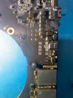
I have visible corrosion around the components shown in the attached files but I am confused by the boardview in that location. The components in the boardview file are shown installed at angles that are not present on my physical board and appear to be different. This is what is throwing me off in moving forward at this point... do I have a slightly different board, or am I not understanding the boardview diagram?
I'm attaching 3 images. A view of my physical board and the corrosion present, a stock image of my board with the area in question circled, and then the boardview file circled in the same area which seems to show a different layout (unless I have some ignorance about this).
I guess I should also mention I have a Fluke 289 as my meter and I DO actually have a thermal camera although the one that I have is more geared toward building maintenance and construction I think it is sufficiently sensitive to be of help in making diagnostics.
I am new at this. My kitty cat spilled a glass of wine on my Macbook. Recently divorced and ex took like 80% of my assets and is still suing me ---- and I need this laptop to defend myself. The 20% I "got" is tied up in my house. Anyway - I have to fix this on my own if I'm going to have access to my files. I'm fairly logical and think I'm capable. I have a hot air station and have done quite a bit of soldering as I've built drones before, but I've only done minimal SMD work.
My charger doesn't light up when plugged in, and I do have a USB-C meter which shows the board is stuck at 5v and draws .006 amps.
I have my boardview and schematics and I have confirmed there is a short between ground and my PPBUS-AON.
I have visible corrosion around the components shown in the attached files but I am confused by the boardview in that location. The components in the boardview file are shown installed at angles that are not present on my physical board and appear to be different. This is what is throwing me off in moving forward at this point... do I have a slightly different board, or am I not understanding the boardview diagram?
I'm attaching 3 images. A view of my physical board and the corrosion present, a stock image of my board with the area in question circled, and then the boardview file circled in the same area which seems to show a different layout (unless I have some ignorance about this).
I guess I should also mention I have a Fluke 289 as my meter and I DO actually have a thermal camera although the one that I have is more geared toward building maintenance and construction I think it is sufficiently sensitive to be of help in making diagnostics.


 I think my heat gun has like waaay less power than the ones shown in your videos it takes mine a long long time to get things to lift, even with preheating.