820-2330 No S3

Bouba148

New member
Hi RRG team,

I have a 2330 board that doesn't turn ON
History: doesn't turn ON after battery replacement ( what I've been told )
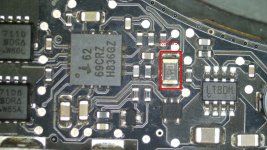
When received No PPBUS , no Green light and R6905 very Hot, but still mesuring 47,5Ohms Could you please check the attached picture and give me your opinion regarding it.
Then I replaced U7000 and now:

PPBUS_G3H : 12,26V LOW? should be 12,56V no?
PP3V42_G3H :3,415 green light OK
PP3V3_G3_RTC :2,806V
SMC_RESET_L: 3,413V
RTC_CLK32K_XTALOUT: Nice 32KHZ Wave.
CHGR_ACOK : 3,235v

PP3V3_S5: 3,313V
PP5V_S3: 0V
ALL_SYS_PWRGD : Pulse at 0,083V then 0V

Of course I'm shorting SMC_ONOFF_L to GND to turn ON the board.
 

Attachments

  • R6905_2330.jpg
    R6905_2330.jpg
    199.6 KB · Views: 0

2informaticos

Administrator
Staff member
Do you get 1.05V at L7770?
If not (0.3V maybe), change C7771, as usual issue...

Check voltage and resistance to ground at battery bus, SCL/SDA.

Why did you change U7000?
Check if is properly soldered...
 

Bouba148

New member
Hi 2informaticos,
thanks for replying,
I have 1,108V at L7770

I've replaced U7000 because i had no PPBUS, no PP3V43 plus the U7000 looked fried. Why? do you think i shouldn't replace it?
At battery bus
Check voltage and resistance to ground:
SCL: 3,412V 6,34K
SDA: Pulsing, then when checked with the scope i have kind of square signal but pulsing to ground. and 30,90KOhms to ground.
maybe it's because no battery was plugged then there no communication between the battery and the board.

I did an SMC reset Test :
-shorted SMC_ONOFF_L to GND
-plugged the charger with keeping SMC_ONOFF_L to GND during 10sec ( no green light )
-released the short
-and shorted it back but just a pulse
and then both fan spinned at full speed then i took some mesurement:

PPBUS: 12,26V
PP5V_S3: 4,969V
PPVCORE_S0_CPU: 0,986V
PPVCORE_GPU: 0,904V
PPVTTDDR_S3: 0,752V
PPVCORE_S0_MCP_REG: 1,003V
ALL_SYS_PWRGD : 3,302V

I can turn it ON/OFF as long as i don't unplug the charger
 
Last edited:

2informaticos

Administrator
Staff member
So it starts in SMC bypass mode.
Means some current, or voltage sensor is out of range.
Check them at pag46/47.

Any sign of life in SMC bypass mode?
USB mouse gets light?

On battery bus is normal to get pulses, even if battery is not connected.
SMC monitors the bus constantly...
 

Bouba148

New member
Yes usb mouse has light in SMC bypass mode.
What do you mean out of range?
What should i have for CPUVCORE_HISIDE_IOUT because I mesure 0V, and it's not shorted to ground.
At U5388: PP3V42_G3H_CPUCOREISNS, PPVIN_S5_CPU_IMVP_ISNS, PPVIN_S5_CPU_IMVP_ISNS_R are present R5388 is 0,2 Ohm.
R5335 mesures 3,937K instead of 4,53K but i would say that it4s not critical.
 

Bouba148

New member
OK, this in SMC bypass mode right ? Because in normal mode many of the sensors are powered by "S0" voltage , that we know the board doesn't reach.
Thanks
 

2informaticos

Administrator
Staff member
Sensors have the same values in normal mode, or SMC bypass mode.
These values are just ignored by SMC when it is bypassed.

As your board doesn't start, then should be some S5 sensor wich blocks the SMC.
So we are interested in these ones.
Start checking pins 9 & 15 of ISL6258...
 

Bouba148

New member
By the way on U7000: Resistance 17/18 is around 52 Ohms and is R052 mesures 25.6 and 7051 mesures 26 but regarding the schematic it should be 10 ohms each. Strange no?
I was sure that i'd posted that info but when i had a look at the beging of the topic it wasn't the case.....sorry my fault.

So these are the mesures you ask.....don't hesitate to correct me if i've missed something....thanks

CHGR_AMON: 0.034V R5380:OK traces OK to SMC
CHGR_BMON:0.034V R5330: OK R5391: 4.165K (OK) traces OK to SMC
Compared with a good 820-2327 MBP13 and I have the same mesurements

S5 sensor to SMC :

SMC_CPU_HI_ISENSE: 0.003V with only the charger plugged and in smc bypass mode 0.097V in smc bypass mode.
SMC_CPU_FSB_ISENSE: 0V with only the charger plugged and 0.268V in smc bypass mode.
SMC_BATT_ISENSE: 0.030V and the same in smc bypass mode

all the aothers sensor rails are not in S5 right?

Also I've tried to replace back the board and turn in smc bypass mode: it turns off as soon as it start the dislay , sometimes i can see the apple, i've disconencted the elements (cd drive, hdd etc.....the best result i had was without the ssd in smc bypass mode : it displayed the question mark )


I've replaced both Resistances R7051 and R7051 with 10 Omhs now resistance 17/18 is around 21 Ohms but still in the same state: NOT TURNING ON......except in smc bypass mode.
 
Last edited:

Bouba148

New member
SMC_PBUS_VSENSE: 0V and 0.001V to 0.005V in smc bypass mode
SMC_DCIN_ISENSE: 0.031V and 0.001V to 0.005v in smc bypass mode
SMC_BATT_ISENSE: 0.036V and 0.034v in smc bypass mode (already posted that voltage higher i think)
 

Bouba148

New member
here we go

1: GND
2: PBUSVSENS_EN: 0V normal depending of S3 state: PM_SLP_S3_L_R
3: PPBUS_G3H_VSENSE: 0V
4: PPBUS_G3H: 12.25
5: PBUSVSENS_EN_DIV : 12.13V
6: PBUSVSENS_EN_L: 12.01V can't short to ground because of Pin 2 (no S3)
 

2informaticos

Administrator
Staff member
Are you using original 85W Apple charger?
If not, try to start with battery connected too, if is good.

Also change C7771, as it always gives problems at the end...
 

Bouba148

New member
Yes it's an official 85W charger
and just 2 minutes before i read your answer i was mesuring again voltage at C7771 and have a nice 1.106V
Then i plugged another official 85W apple charger and suddenly the volage dropped to 0.350V, so i wondered that C7771 was margin then i've replaced it but still the same, then i replaced it once more with 2 150uF in parallel, still mesuring 0.350V.
I've also mesured all the capacitor taken out / replaced , all have good mesuring ( within the tolerance )........

Now it doesn't turn on in SMC bypass mode
So what do you think?
 

Bouba148

New member
I replaced that capacitor one more time to be sure but still the same.
I removed L7770 and I have no voltage on pin 1 which mens that U7750 doesn't provide any power.
This one has PPBUS_G3h on pin 1 vcc, and he's told to turn ON as it has 1.495V on pin 4
I've notied that it gets very hot tme to time and make the green light disapear , certainly goes in short to ground.

I'll have to order it or get on from a donor board asap
 

2informaticos

Administrator
Staff member
You cannot test a buck converter without its coil.
0.3V there is sign of bad C7771.
Google search can help you to change it with normal size capacitor.
If you use same small size package, don't remove it from scrap board in the same position.
 

Bouba148

New member
Hi, Im' back with that board as I received the U7750......

So I stopped at: bad U7750 because very hot and killing the green light and 0.3V at C7771.
First things first: replaced the U7750 green light OK and PPBUS_G3H 12.30V but still 0.3 at C7771V.

Replaced one more time C7771 from a GOOD WORKING BOARD: still 0.3V ( So far I think I've replaced that capacitor at least 4 times and i'm pretty sure that it's not coming from there but you guyz are the experts).
I've double checked all the U7750 pins to be sure that they're soldered correctly: OK
Replaced C7776 still the same,

Downloaded the datasheet of the U7750 and tried to see the role of each pin.
Also just remind you that P1V05S5_EN U7750 Pin 4 is OK with 3.322V
Someone does know about P1V05S5_ISEN on PIN 9 going through R7779 which is 2.428Ohms OK.

Thanks
 

2informaticos

Administrator
Staff member
Post voltages U7750, pins 1, 2, 12, 4, 6.
Be sure C7770 is in place. R7751 is there?
Pay atention to R7780/81.
Resistance to ground L7770?
Be sure to solder C7771 in correct way, is bipolar.
Check the traces between all components there...
 

Bouba148

New member
U7750 voltages:

Pin1: 12.57V
Pin2: 5.062V
Pin 12: 5.053V
pin 4: 3.315V
pin 6: 0.599V

C7770 in place, R7751 in place and mesure 5 ohms OK

L7770 resistance to gnd : 265 Ohms VS 430 Ohms GOOD WORKING BOARD
C7771 mounted and soldered correctly
 
Top