
-
For $29/mo, we provide access to advanced level technicians who will answer your questions on any Macbook board related matter to the best of their knowledge promptly & walk you through how to solve your problem so you can deliver a working board to your customer.Subscribe Now
You are using an out of date browser. It may not display this or other websites correctly.
You should upgrade or use an alternative browser.
You should upgrade or use an alternative browser.
820-2330 No S3
- Thread starter Bouba148
- Start date
Change Q7770/71 and be sure all the trace OK in that area.
BTW, stop to measure Gate for buck converter MOSFETs...
BTW, stop to measure Gate for buck converter MOSFETs...
Gate measurement is useless.
If OK, you can see oscillation; doesn't help for workink board.
If not OK, no oscillation; doesn't help, you already knew the board is not OK.
So, why to measure there???
You still miss something there, or MCP is dead and blocks that power rail...
If OK, you can see oscillation; doesn't help for workink board.
If not OK, no oscillation; doesn't help, you already knew the board is not OK.
So, why to measure there???
You still miss something there, or MCP is dead and blocks that power rail...
smiba
New member
If you're still having the issue that the MCP voltage isn't at the right range but around 0.2V - 0.8V make sure to replace C7771 with a NEW capacitor.
All these capacitors will die over time and getting them from a donor board probably doesn't make them much healthier.
Measure resistance from C7771 (MCP Rail) to ground, then desolder C7771 and do the same measurement to ground. (Make sure to wait until the resistance stabilises)
You will probably find that the resistance without C7771 goes up by almost half because this capacitor is leaking power away to ground combined with reduced capacity.
If you don't want to do the scratching just get a replacement capacitor from farnell (or whatever distributor you want to use), they have perfectly fitting tantalum capacitors. (However these caps will also most likely die again in a few years). Only cost a few bucks and you will use them in the future on other repairs of this exact same board!
Bouba148
New member
Replaced U7750 still the same, replaced C7771 again for maybe the 10th time from different donor board different size and different place and you know what: it's working NOW
You can mark this topic as solved and close it.
AGAIN THANKS FOR ALL YOU GUYZ FOR YOUR TIME AND PATIENCE.
You can mark this topic as solved and close it.
AGAIN THANKS FOR ALL YOU GUYZ FOR YOUR TIME AND PATIENCE.
Bouba148
New member
Hi Guyz,
The MBP came back , but this time for another reason that is maybe linked to what I did during the repair process , I explain:
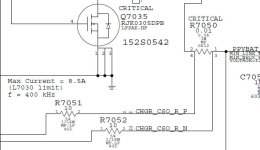
No the board is not chargng the battery, it is detected but stays at 0%.So my first tought is for the current sensing resistors attached to pin 17/18 of U7000.
If you remind correctly, previously ( higher in the post ) i was complaining that R7051 and R7052 were around 50 Ohms each instead of 10 Ohms each as it is in the schematics I have, so before the board was fixed, i put there 2 nice 10 ohms resistors.
Question: Could the issue is coming from there? Why this 820-2330 A board was equiped with 50 Ohms resistors but in ALL the schematics
Thanks
The MBP came back , but this time for another reason that is maybe linked to what I did during the repair process , I explain:
No the board is not chargng the battery, it is detected but stays at 0%.So my first tought is for the current sensing resistors attached to pin 17/18 of U7000.
If you remind correctly, previously ( higher in the post ) i was complaining that R7051 and R7052 were around 50 Ohms each instead of 10 Ohms each as it is in the schematics I have, so before the board was fixed, i put there 2 nice 10 ohms resistors.
Question: Could the issue is coming from there? Why this 820-2330 A board was equiped with 50 Ohms resistors but in ALL the schematics
Thanks
Attachments
First of all, I recommend to try other known good battery.
Be aware of new "fake" chinese battery; test with used original one, if possible.
Check the battery state in System Report...
Be aware of new "fake" chinese battery; test with used original one, if possible.
Check the battery state in System Report...
Bouba148
New member
So As I haven't another battery "under the hand" to took the susposed non charging battery and tested it in mbp 13 of 2008 ( same generation ).
The other machine turns on directly on the battery only and displayed the level :65%.
Checked the LID leds: OK
plugged the charger and after a little moment 1 or 2 min the level passed to 66%.
So I would say that issue is coming from the board:
In the mean time I've put back 2 47 Ohms resistors for R7051 and R7052 but still the same.
Also If i plug that "bad" board to that battery and turn ON the board with the charger, it stays ON when i remove the charger
Last edited:
Post CHGR_AMON and CHGR_BMON with both charger and battery connected.
Be sure you have ISL6258A, not 59...
Be sure you have ISL6258A, not 59...
Possible some traces, or resistors corroded...
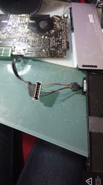
Disconnect BIL conector (J6955) and see if charge.
Also check BIL connector for corrosion.
Check resistance to ground on SCL/SDA lines.
Should't have NO more than 1% difference.
Remove D6950 if needed and compare again the values.
Disconnect BIL conector (J6955) and see if charge.
Also check BIL connector for corrosion.
Check resistance to ground on SCL/SDA lines.
Should't have NO more than 1% difference.
Remove D6950 if needed and compare again the values.
Last edited:
Bouba148
New member
Hi,
All what i posted before was WITHOUT the BIL board connected.
I've Checked resistance to ground on SCL/SDA lines and both are 30.22 and 30.29 KOhms.
But what I've noticed is that I don't have communication on SCL line: it's always a solid 3.41V versus square signal on the SDA line.
I checked R5281(pull-up resistor ) this one is OK and correctly connected to J6950 and J6955 and to U7000........so maybe not correctly connected to the SMC or the SMC /U7000 not talking to the battery.
I think I'll replace the U7000 first and see......
What do you think?
This difference looks to big for me...
Remove D6950 and check again.
Remove D6950 and check again.