A1466 Early 2015 820-00165-A board problem

Askaleto

Member
Hello Macbook repair experts.
First of all, I have virtually no experience with repiring macbooks and this is my first one with faulty logic board. I do have limited experience with repairing PC laptops.
I watched many youtube videos from Louis Rossmann channel, so the concepts are clear to me.

So, I have on my desk Macbook Air A1466 EMC2925, Early 2015 with faulty motherboard. The customer said that it was working fine until it failed to update from Catalina to Big Sur. When plugged charger laptop starts with very loud fan noise but no chime and no POST and image. So it is "braindead".

When I opened laptop, I noticed that the board is very clean with tiny trace of corrosion (green) on one place on the board and what I noticed immediately is that there was some kind of previous repair attempt. The load switch U8030 was desoldered and removed from the board. After visual inspection I cannot determine if something else is removed but it seems not.

First of all, is it possible Macbook Air to work without U8030?

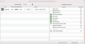
Logic board is removed from teh laptop and it is conencted only with I/O board (because of charger). When charger is conencted to the board there is a green light which soon becomes orange and fan starts working at full speed. That is basically all.

I have performed some measurements on the board and this is what I have:
PPBUS_G3H = 8.56V
PP3V425_G3H = 3.42 V (also indication on the charger).
PP3V3_S0 = 0.54V ->this is problem
PP3V3S0_EN = 3.23V (there is enable on U830, but the chip is removed in previous repair).
PP5V_S0 = 5.12V
PP3V3_S4 = 3.32V
PP3V3_S5 = 3.32V
PP3V3_SUS = 3.32V
PP3V3_S4_FET_R = 3.32V
PM_SLP_S3_L = 3.31V
PM_SLP_S4_L = 3.32V

On coils L7310 and L7320 I measure 0.0V, but I could swear I saw once 1.7 V (after many charger plugging/replugging)

This problem reminded me to the one described here: https://boards.rossmanngroup.com/th...er-issue-on-pp3v3_s0-or-something-else.26755/

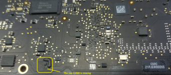
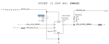
The corrosion (green color) was around C1930 and this caps is not present on the board. There is a resistor R on which R1931, on which I measure 10.8 kohm and 1.05V

I have also measuren on C7711 (line PP3V3_S0) toward ground in diode mode and reading is 387, which means there is no short to ground on PP3V3_S0.

Currently I don't have spare U8030, and I wonder could I short (bridge) input and output pins on the board in order to send PP3V3_S5 to PP3V3_S0_FET_R?

I have found on some other forums that when PP3V3_S0 was missing that troubleshoot procedure also removed U0830, but don't understand exactly why.

Right now, I have 0.54V (stable) on PP3V3_S0 line. All measurements are very stable (or my multimeter is very slow to react to sudden changes if any).

I I hope you'll be able to help me.
 

Attachments

  • Corrosion part.png
    Corrosion part.png
    941.3 KB · Views: 4

piernov

Moderator
Staff member
Buy donor board and replace missing/corroded parts.
Of course it doesn't match with the history of dying after macOS upgrade (which would rather be corrupt SPI ROM for example), so either customer isn't telling the truth or you don't have the original board of that MacBook in front of you.
 

Askaleto

Member
Hello piernov and thank you for your reply. Yes, I concluded the same regarding the history. As for corroded parts, there is a trace of teh corrosion only on place of C1930. This cap is no longer on the board and I don't think it is necessary to find a replacement cap. I do have PP1V05 and it is stable 1.05V. This cap is filter on PP3V3_S5. So the board should work without that cap. But I wonder about U8030 chip?

So, the board cannot work without U8030, is that right conclusion?
 

Attachments

  • C1930.png
    C1930.png
    37.2 KB · Views: 1

piernov

Moderator
Staff member
Always replace corroded components and don't leave them off, this is the basis of quality work. The machine can work even if certain caps are missing (and sometimes even other components), but it doesn't apply to all of them, and the machine can get unstable if it's missing caps.
 

Askaleto

Member
Ok, but right now for the purpose of testing and ruther troubleshooting, is it safe to short PP3V3_S5 to PP3V3_S0_FET_R on the place of missing U8030, just to see what is further behavior?
 

Askaleto

Member
In addition to previously described, I have noticed that voltage on C6950/6951 which is PPVBAT_G3H_CONN oscillates. No battery is connected, the board with I/O board is on the desk. I measure 8.56 then it goes down to zero and then back to 8.56 and so on. But voltage on F7140 (PPBUS_G3H) is stable 8.56 V. Not sure if that is significant in any way.
 

2informaticos

Administrator
Staff member
Do not check battery connector pins, if there is not battery present.
PPBUS_G3H is correct, do not waste time in U7100 area.

U8030 is critical, place it back!
You can try bypassing it, but SMC can detect overload and stops the board; may need to start in SMC bypass mode, only for test.
 

Askaleto

Member
Hello 2informaticos,
I have order a donor board and will try to replace the U8030. It will take a couple of days.
 

Askaleto

Member
Since U8030 is a load switch TPS22924C with the following characteristics: current = 2A Max, Ron = 25.8 mOhm at 2.5V and it will take more than a week to be delivered, I was thinking to use an alternative one with (what it seems to me) better characteristics. I think I can use FDS6676AS N channel MOSFET. This chip is significantly bigger than original, but there is more than plenty space on the board. I was thinking I can make something like shown in the attached picture. Someone may consider this doggy, but it could work.

Please tell me what you think.
 

Attachments

  • Alternative Load switch.png
    Alternative Load switch.png
    235.2 KB · Views: 3

Askaleto

Member
At first glance, I rejected this idea, because I need to have MOSFET ON at 2.8 V( 3.23V-054V). But I saw that typical treshold voltage is 1.5 V and max 3 V for this MOSFET, so I made little experiment on a desk and it opens on about 2.7V, which is really at the edge. Probably, this will sometime works and sometimes doesn't depending of the temperature. But since I have a few PC notebook boards, I found one more type used and that is AON7408 30V N-Channel MOSFET . This is also on the edge, but on the schematics I found that this creates 1.2 V. Perhaps, I'm interpreting something wrong, but that is why I'm asking before actual testing. Like Louis said in one of his youtbe videos "Never be afraid to show to others how dumb you are" :)
 

Attachments

  • Datasheet _alternative.png
    Datasheet _alternative.png
    15.1 KB · Views: 1

2informaticos

Administrator
Staff member
Get correct chip replacment and stop to waste your time.
A power MOSFET requires 5-10V for Vgs to work properly.
Lower voltage will mean higher internal resistamce and can be fried.
 

piernov

Moderator
Staff member
You need to have at least some electronics knowledge to be able to fix a device as complex as a Mac logic board.
As the name says, Vgs is voltage between gate and source. If you have 3.3V with respect to ground on source, it means you need 3.3V + Vgs on the gate with respect to ground. Also an ideal MOSFET doesn't exist, the on-state resistance progressively increases when Vgs decreases (ie. low Vgs = higher losses = higher power dissipation).

Please stop messing with customer's boards worth $300. Additionally performing low-quality repairs is the perfect way to discredit the whole third-party repair industry. If you watched a lot of Louis Rossmann videos, these concepts should be clear as well.
 

Askaleto

Member
Hello,

donor board arrives next Monday. In the meantime I thought to try to find an alternative solution. Never repair Mac before and I have a lot of PC laptop boards.
I'm not messing with anything except maybe MS Paint. Everything that came to my mind I asked here first.
This alternative idea was more likely Sorin's approach :)

Anyway, next Monday, I'll know more. I have found almost identically problem here on the forum (link pasted in the first post), but the solution is not clear. I don't know what it means that Jtag connector was source of the problem.
 

2informaticos

Administrator
Staff member
Corrosion underneath J6100 can block correct communication between PCH and BIOS chip (U6100).
You must replace missing components first.
 
Last edited:

Askaleto

Member
Ok guys, here is the update. The donor board arrived faster than I expected. I have removed TPS22924 load switch from the donor board and I managed to solder it on the faulty board. This was no easy, since my hot air rework station is not exactly state of the art and the chip is 1.4 mm x 0.9 mm. At one point, I even consider to give up. Eventually, it was soldered successfully, and after that I had PPV3V3_S0 and ALL_PWR_GOOD. The vcore voltage on the coils phase 1 and phase 2 were 1.25V. I have connected everything and the MacBook Air booted up very nicely. Everything seems to be fine. I have played with the laptop for about an hour and after next power on fan was running at full speed, but computer booted normally and I could work without any problems. I have tried to reset SMC but that didn't solve the problem. I have installed Macs FAN control and all temperatures were OK, when I put fan speed on auto based on sensor based, rpms went significally down. I even type this post from this MacBook Air. Max temperature is Intel GPU 40 degrees C. So it seems that this is not a hardware problem as I thought at first place, but I know that I need some special diagnostic software to read all sensors.

So my next question, before concluding this job is could be this possible still a sensor issue. If some sensor is bad (for example plan rest sensor), would it fan still run full sped even Macs fan control app is installed?

Thank you.
 

Attachments

  • Temperatures.png
    Temperatures.png
    69.5 KB · Views: 0

2informaticos

Administrator
Staff member
Possibly ALS problem.
Disconnect webcam and test again.
You should also test another trackpad flex/board; clean first the contacts of the flex.
 

Askaleto

Member
Hello 2informaticos, is ALS ambient light sensor or something else?
Is there any way I can read sensors data or test it myself. I've seen this can be done in ASD, but I'm not sure how exactly.
 

Askaleto

Member
Ok, I have removed the the connector from the web cam and everything is the same. I also brushed the contacts of the flex cable for trackpad with alcohol a bit and that didn't help either.
Yesterday, everything was working fine for about and hour or two, then fan suddenly increased the speed. Webcam, trackpad and everything else seem to work just fine.
I don't have another trackpad to test, MacBooks here are very rare. Interesting, when laptop is first powered ON fan is not at full speed until loading Mac OS Big Sur approximately at half progress bar. Then it starts full speed. Also, when I choose restart, it immediately goes full speed during laptop restart.

Is there any way I can read the data from sensors to know if this is a failed sensor?
 

Attachments

  • Screenshot 2021-02-13 at 11.16.36.png
    Screenshot 2021-02-13 at 11.16.36.png
    33 KB · Views: 1
Top