RESQ-MYTECH
New member
Hi all. Not frequented the forum for a while as been getting along with the Macbook repairs quite well. So an overdue helloooo. Anyway, those that have read my posts know it is not going to be a short one... here goes.
Above mentioned Macbook pro is given to me for repair. Presented with no display. Upon opening, logic board is immaculate with the exception of a little corrosion on J6601. TBH, I feel it was a "little" to clean.
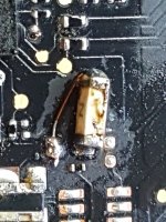
Done the checks of shine a light onto the screen and the image is there, so I know it is backlight related. Tested pin 1 of J8300- no volts at all ( 0.001). traced pack as far as F7700. Checked the fuse and this was OK ( no surprises there). Pin 1 had 12.6v and pin 2 had 1.608v. Thus indicating a short. Pins 1-4 on R7700 had 12.6v and pins 3 and 4 of Q7700 has 12.6v where as pins 1/2/5/6 had zero volts. Literally zero. So I swapped Q7700 for one from a donor board. Still the same. Followed back to U7700 and saw evidence of flux there. I now feel that the board may have been looked at before. My soldering is not the best but I decided to swap the U7700. Still had the same readings as before. I then noticed that R5455 was not next to F7700. Looked on the schematic ( page 40) and it shows R5455 being there for the LCD Backlight Current Sense circuit. So I got a resistor of the same value and put it on. I feel it should have been there as the pads were populated with solder. Also C5450 was also not there. But I feel this was never there due to the pads only having a small amount of solder there and the copper pad showing around it. see image 1. Excuse the fuse, I will explain further on about that. Again the schematic shows this as being there. But I decided due to the pads not to fit this. Its at this point I think I may have f**ked up. Connected the power and F7700 popped. I lost PPBUS_G3H. No Green LED, no 8.6v ( even though pin 1 of F7700 was showing 12.6v). Anyway, managed to resolve the PPBUS_G3H issue and got power back at 12.6v. This has confused me even more as the schematic says PPBUS_G3H should be 8.6v. I get 12.6v at pin 1 of F7700 with the same voltages at R7700 and Q7700 across all pins. The was also 12.6v at pin 1 on J8300. I know that pin 1 on J8300 should be in the 25v area ( i think). Connected the screen and power, screen flashed and F7700 popped. At this point I am out of fuses. Hence the 0802 fuse soldered to pin 1 and jumpered to pin 2. Yeah, troll me but it worked. But I now have the 12.6 on pin 1 and 1.6 on pin 2 of F7700. Thus indicating the short again. I have managed to find the culprit. It was C7768 as shown on FlexBV. done a search on the schematic for C7768 and it comes up not found. on the schematic I suspect it to be C7710/7711/7712 but not sure which. I have removed C7768 and the short is gone but still only getting 12.6v up to pin 1 of J8300. connect a screen and still have image but no backlight.
My head hurts.
So.... questions:-
1/ I have got the schematic and BV in the same file however some of the designations do not correspond. Am I being trolled by this?
2/ what am I missing in respect of the low power to pin 1 on j8300? I have watched Louis's video explaining what the voltages should be and different values will indicate the issue, but I think I missed the 12.6v reason.
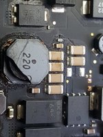
3/ in image 2 it shows L7710 has a cracked top but the voltages pin 2 is 12.27v and pin 1 is 12.28v ( minor difference). You can also see in this image the cap I removed C7768. Could this cracked coil be the cause of my issus?
As usual and assistance is greatfully received.
Thanks in advance.
Marc
Above mentioned Macbook pro is given to me for repair. Presented with no display. Upon opening, logic board is immaculate with the exception of a little corrosion on J6601. TBH, I feel it was a "little" to clean.
Done the checks of shine a light onto the screen and the image is there, so I know it is backlight related. Tested pin 1 of J8300- no volts at all ( 0.001). traced pack as far as F7700. Checked the fuse and this was OK ( no surprises there). Pin 1 had 12.6v and pin 2 had 1.608v. Thus indicating a short. Pins 1-4 on R7700 had 12.6v and pins 3 and 4 of Q7700 has 12.6v where as pins 1/2/5/6 had zero volts. Literally zero. So I swapped Q7700 for one from a donor board. Still the same. Followed back to U7700 and saw evidence of flux there. I now feel that the board may have been looked at before. My soldering is not the best but I decided to swap the U7700. Still had the same readings as before. I then noticed that R5455 was not next to F7700. Looked on the schematic ( page 40) and it shows R5455 being there for the LCD Backlight Current Sense circuit. So I got a resistor of the same value and put it on. I feel it should have been there as the pads were populated with solder. Also C5450 was also not there. But I feel this was never there due to the pads only having a small amount of solder there and the copper pad showing around it. see image 1. Excuse the fuse, I will explain further on about that. Again the schematic shows this as being there. But I decided due to the pads not to fit this. Its at this point I think I may have f**ked up. Connected the power and F7700 popped. I lost PPBUS_G3H. No Green LED, no 8.6v ( even though pin 1 of F7700 was showing 12.6v). Anyway, managed to resolve the PPBUS_G3H issue and got power back at 12.6v. This has confused me even more as the schematic says PPBUS_G3H should be 8.6v. I get 12.6v at pin 1 of F7700 with the same voltages at R7700 and Q7700 across all pins. The was also 12.6v at pin 1 on J8300. I know that pin 1 on J8300 should be in the 25v area ( i think). Connected the screen and power, screen flashed and F7700 popped. At this point I am out of fuses. Hence the 0802 fuse soldered to pin 1 and jumpered to pin 2. Yeah, troll me but it worked. But I now have the 12.6 on pin 1 and 1.6 on pin 2 of F7700. Thus indicating the short again. I have managed to find the culprit. It was C7768 as shown on FlexBV. done a search on the schematic for C7768 and it comes up not found. on the schematic I suspect it to be C7710/7711/7712 but not sure which. I have removed C7768 and the short is gone but still only getting 12.6v up to pin 1 of J8300. connect a screen and still have image but no backlight.
My head hurts.
So.... questions:-
1/ I have got the schematic and BV in the same file however some of the designations do not correspond. Am I being trolled by this?
2/ what am I missing in respect of the low power to pin 1 on j8300? I have watched Louis's video explaining what the voltages should be and different values will indicate the issue, but I think I missed the 12.6v reason.
3/ in image 2 it shows L7710 has a cracked top but the voltages pin 2 is 12.27v and pin 1 is 12.28v ( minor difference). You can also see in this image the cap I removed C7768. Could this cracked coil be the cause of my issus?
As usual and assistance is greatfully received.
Thanks in advance.
Marc