A1706 no power

2informaticos

Administrator
Staff member
Don't waste time repeating checkings on the same power rail.

What about C7834 voltage?
Also check C7880.

Post SMC_PM_G2_EN, PM_BATLOW_L, SMC_ADAPTER_EN, PCH_INTRUDER_L, RTC_RESET_L, PCH_SRTCRST_L voltages.
 
PositionVoltage (V)
C78341.25
C78802.64
SMC_PM_G2_EN (at R8110)3.42
PM_BATLOW_L (at R1451)3.35
SMC_ADAPTER_EN (at R5185...?)0.00
PCH_INTRUDER_L (at R1401)I saw 2.39 at first (maybe a mistake?), but now I just see 0.20
RTC_RESET_L (at C1531)0.26
PCH_SRTCRST_L (at C1530)0.26
 

2informaticos

Administrator
Staff member
Seems to have 3V0_G3H problem; it should be steady 3V.
Remove C7880 and check voltage again.
If still low, remove C1227/8 (one by one) and see if voltage goes up.
 
OK great. I'm going to need to practice some on my junk board before I attempt this removal. I'll try to watch some videos on this. If there's any common resource for proper technique on this that you usually direct people to, let me know.
 
OK, so let me get this straight. I looked at a video (timestamp 11m15s,
) where Louis removes a capacitor. Here's what I see:
  • Hot air tweezers grip the edges of the capacitor
    • What temperature should the tweezers be? (I see that 63/37 solder melts at 183 °C, but I assume you run the tweezer some amount hotter)
    • What temperature should the hot air be? (I am imagining that I might be able to crudely replicate this with a heat gun, but maybe this is a bad idea)
  • The hot tweezers are then used to melt and direct the flow of leaded (correct?) solder until the capacitor is engulfed in the solder and comes off with gentle pulling
  • The tweezers are then used to scratch/clean the exposed contact points; I see that a little bit of (I think) solder PASTE (correct?) is also applied here (I had trouble distinguishing the blunt needle from solder wire at first)
Does this all sound correct?
 
OK, based on my experiments on my junk/practice board, the answer to the soldering iron temperature is "as hot as the thing will go" (allegedly 450 °C, but this is just a cheapo soldering iron that was already available to me at work... not sure how accurate it is). Since this is not a nice hot air tweezer setup, it seems easiest to just apply a bead of solder at the capacitor first, and then to get set up with regular tweezers and the soldering iron using the already-delivered solder to facilitate heat transfer and release of the capacitor. I am definitely able to pull small capacitors off the junk board.

How important is it to have replacement capacitors already available when I do these removals? Will surface oxidation be a big problem if I remove the capacitors to diagnose the problem but then need to wait several days for capacitors to arrive? Or can I generally recover/reuse capacitors that are found to still be good?
 
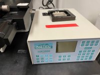
You mentioned a pre-heating pad being useful and provided an example product link. I have a heated stage (pic attached) that goes to at least 200 °C, probably higher. I also have a heat gun.

My question is about how you apply the heat. Like, with the heated mat you linked, do you just put it on top of what you will be working on? In that case I guess my thing wouldn't work so well. For the heat gun, how hot is too hot? I know in principle that if I had it above the melting point of the solder that would be too hot because it would cause things to melt indiscriminately. Is there a temperature you recommend? Is there anything I need to be extra careful to not inadvertently heat with it?
 

Attachments

  • IMG_5524.jpeg
    IMG_5524.jpeg
    303.1 KB · Views: 2

2informaticos

Administrator
Staff member
The one you've pictured, is useless.
The pad I mentioned must be placed under the board and preheats it even; 100-110 degrees is good enough.
Stop it, once you start to work with the hot gun; but maintain it under the board.

No real recommendation about hot air station.
Each one has its partivularities and you must practice in scarp board first.
I usually use my Hakko FR-810 at 400-450 degrees and 2-3 air flow; when I don't use preheater.
 
Seems to have 3V0_G3H problem; it should be steady 3V.
Remove C7880 and check voltage again.
If still low, remove C1227/8 (one by one) and see if voltage goes up.
Following removal of C7880, voltage for 3V0_G3H remained about the same (2.65 V).

Following removal of C1227 (and incidentally also C1208 and C1223 because I'm not very good at doing this yet--they were neighboring capacitors), voltage remained about the same (2.64 V).

Following removal of C1228 (and incidentally also C1531...), it is now showing 0.25 V.
 

2informaticos

Administrator
Staff member
Voltage shouldn't drop removing capacitors.
You did something wrong on the board.

The main problem can be U7800, or U0500.
But now you must find what another problem did you cause on the board.
 
OK, I think the problem is that some solder had drifted over to around C1225/R0862/R1453; I was able to clean this up somewhat, although C1225 came off in the process. The reading for 3V0_G3H is now reading 2.64 V again.

So now, regarding the main problem being U7800 or U0500, how should I go about diagnosing that? Thanks!
 

2informaticos

Administrator
Staff member
What is actual voltage fort RTC_RESET_L and PCH_SRTCRST_L signals?
Should be close to 3V0_G3H level; even if this is lower than normal.
 
OK, so I found this example video of changing a PMIC [
]. I'm having a hard time hearing the audio of the person in the video, so I apologize if I missed something that was said. I just want to walk through my understanding of the steps to do this--please tell me if any of this is wrong, or if you have any tips.

  • Apply flux to a corner of the PMIC
  • Blow hot air on the flux such that it travels under the PMIC
  • Apply hot air while gently pulling at the PMIC until it comes off
  • Apply more flux to where the PMIC was
  • (At 4 minutes 10 seconds into the video I can't quite tell what is happening, but it looks like....) Use a soldering iron to somehow remove excess solder (?)
Let's focus on the last step I mentioned so far in particular. What is actually happening? Is some fresh solder being applied? What kind? Is there a trick to keeping the solder balled up on the tip of the soldering iron like seems to be shown in the video?
 
Last edited:

2informaticos

Administrator
Staff member
Pufff, the goal of the forum is online assistance on the repair process; not for personal training.
If you want/need personal training, contact via PM.

I recommend to practice on scrap board, before touching any client board.
Use the preheater above mentioned, it will help a lot.

You need to apply leaded solder on the pads and clean them evenly.
Be aware, if board goes cold, you can risk to remove the pads.
 
Got it; thanks for letting me know. And thanks for still providing the useful advice just now, even though it is beyond the scope of what this forum is supposed to be about.
 
Top