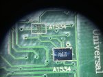
MacBook 12" 2016 820-00244 not power on

waterchill

Member
Good day friends, so I have here this MacBook which is drawing 20V 180mA only the Mainboard and 1,4A with battery. No Apple logo no boot. Here are some voltages:

PPBUS_G3H = 8,70V
PP3V3_G3H = 3,30V
PPDCIN_G3H = 19,7V
PP3V3R3V0_AON = 3,3V
PP5V_G3H = 5,1V
PP5V_S4 = 5,1V
PP5V_S0 = 5,1
PP3V3_S5 = 3,3V
PP3V3_SUS = 3,3 V
PP3V3_S4 = 3,3 V
PP3V3_S0 = 3,3V
PP1V8_SUS = 1,8V
PP1V8_S3 = 1,8V
PP1V5_S0 = 1,5V

I found out that PPVCORE_S0_CPU = 0V / 10,5ohms. Checked this with a 2017er MacBook resistance is same but 0,635V. So I have checked:

VCIN of U7210 and U7230 = 5,10V
VIN of U7210 and U7230 = 8,70V

ZCD_EN = 0V = CPUCORE_FCCM

CPUCORE_FCCM is produced by U7100

VIN of U7100 = 8,7V
VCC of U7100 = 5,1V

I don't see an enable pin for U7100. Schematics says for VIN 12,9V I got 8,7V, maybe this is problem or bad U7100? Or something else?

cheers
 

2informaticos

Administrator
Staff member
"PPBUS_G3H = 8,70V"
Was that with battery connected?
You should check with charger alone.

Any history fault available?
You can try known good BIOS; just make backup first.
 

waterchill

Member
"PPBUS_G3H = 8,70V" = without battery only the board alone. Unfortunately there is no history available :( With battery connected around 8,4V
 
Last edited:

waterchill

Member
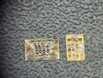
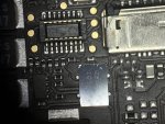
Look like the bios chip is dead. Pls can you confirm that this is the right direction to solder on the board of the ubos2? Anyway I reballed several times and tried both directions but no reaction of the chip.
 

Attachments

  • IMAGE 2023-04-05 15:47:27.jpg
    IMAGE 2023-04-05 15:47:27.jpg
    298.5 KB · Views: 0

waterchill

Member
I have now replaced the SPI Rom, it's not an quick job, because you have to solder and reball after programming. Noticed that there are 2 kinds of chips. Didn't got the original one, but it is possible to turn the chip 90° and it is ok. So now the situation is, that I got no voltages. The only voltage I get is the PPDCIN 5V 3mA. Looks like Q3100 or U3100 is faulty, but why now? This board is driving me crazy...

Q3100:
Gate 1= 10,80V
Gate 2 = 6,90V

I do not understand why the gate have more voltage that the incoming voltage?
 
Last edited:

2informaticos

Administrator
Staff member
CD3215 chip has internal charge pump to control the Gate for N-channel MOSFETs.

Did you solder the chip in the same orientation like it was in MLB?
Did you verify the file after writing?
 

waterchill

Member
Not possible to solder in same orientation because the chip is little bit different. I have to rotate the chip by 90 degrees. File is double checked
 

Attachments

  • IMG_2414.jpeg
    IMG_2414.jpeg
    679.8 KB · Views: 0
  • IMG_2415.jpeg
    IMG_2415.jpeg
    442.6 KB · Views: 0
  • 820-00244-connector.jpg
    820-00244-connector.jpg
    904.6 KB · Views: 0

waterchill

Member
Schematics says Q64FVBYIQ this chip here is Q64FVYIQ this is looks the same. Also Alixpress sales this as the same. This chip I bought 5pcs was sold as the rom for A1534. What I have tried now is multiple times changed the chip, erased sold again, nothing changed. Also tried power without this chip, same behaviour. I don't how is the behaviour of a mainboard without the rom, but I think it should also without the rom switch to 20V or not?
 
Top