For $29/mo, we provide access to advanced level technicians who will answer your questions on any Macbook board related matter to the best of their knowledge promptly & walk you through how to solve your problem so you can deliver a working board to your customer.
"On R7715, I have 2.5V on pin 1, but nothing on pin 2."
Don't you want to get voltage on ground pin, no?
BKL_EN should be 1/3 of PPVIN_S0SW_LCDBKLT, which is (should be) aprox 8.5V.
You should get 2.8V aprox; but even 2.5V is sufficient to enable U7701.
I suppose bad solders for U7701, or bad chip.
Post resistance to ground (diode mode, red probe to ground) for all the connections of U7701.
Use surrounding components as test points...
Hello, yes the pin 2 is GND.
I tested the pins of U7701, no worries, I tested the continuity, see if there were no tracks cut, I did not test the continuity to the ground for all the pins.
I sold a new brand new chip bought on Farnell.
Still no backlight.
I still have 8.5V on XW7720.
"Post resistance to ground (diode mode, red probe to ground) for all the connections of U7701.
Use surrounding components as test points..."
Do that, so we can confirm good solders...
I have tested all U7701 pins to earth, except the GND pins, no other is grounded, no resistance to the multimeter (infinite resistance).
I also took the opportunity to note all the tensions of U7701 with a monitor plug:
1: GND
2: GND
3: 2.5V
4: 2.81V
5: 8.54V
6: 8.55V
7: 8.55V
8: 0V
9: 0V
10: GND
11: 5,10V
12: 0V
13: Impossible to test (I do not see where is the pad to test it)
14: 3.30V
15: 0V
16: 5,10V
17: 0V
18: 3.30V
19: 3.30V
20: 0V
21: 0V
22: 0V
23: 0V
24: GND
25: 0V
You didn't understand.
Diode mode value on the U7701 pins (red probe to ground) will reveal if you have some bad solder.
Please do what we ask, if you expect help.
WE can NOT measure anything on YOUR board...
If I understand correctly, I have to put the multimeter in diode mode, the red (+) on the mass, and with the black (-) I test each point of U7701?
I should have what value if good / bad solder on the multimeter?
Hello,
Sorry for the wait, I was working.
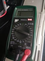
I attach the photo of my multimeter with the diode setting used.
So:
1: .016
2: .016
3: .712
4: .679
5: .824
6: .512
7: .512
8: 1.
9: 1.
10: .687
11: .562
12: 1.
13: I can not test it, no pad
14: .460
15: 1.
16: .562
17: 1.
18: .712
19: .715
20: 1.
21: 1.
22: 1.
23: 1.
24: .016
25: 1.
I flatly change the chip in the end, the same.
Maybe it is actually poorly welded but I even reflect the chip several times and always the same.
Possible that the problem comes on the other hand?
Return lines should gave all same value, 600-650 aprox (diode mode); if chip is properly soldered.
I hope you remember to always ckeck with red probe at ground...
The chip is well soldered, no worries.
Still no backlighting though.
When I run the tests while pressing D at startup I have the error PFM006: the SMC present can be a problem.
I did a reset SMC and PRAM / NVRAM but nothing.