DavutAmana
Member
Hello,
On this board all the power rails for the PM_SLP_S4_L power supply are present but the CPU does not send the signal.
PPBUS_G3H 8,58V
PM_BATLOW_L 3,31V
SMC_RESET_L 3,39V
SMC_PM_G2_EN 3,42V
SMC_ONOFF_L 3,42V
PM_RSMRST_L 3,25V
PM_PWRBTN_L 3,41V
PCH_DSWVRMEN 3,3V
PCH_INTRUDER_L 3V
PCH_INTVRMEN 3,22V
PCH_SRTCRST_L 3,3V
RTC_RESET_L 3,3V
PM_SLP_S5_L = 0V
PM_SLP_S0_L = 0V
PM_SLP_SUS_L = 3,32V
With the multimeter I see a very small 0.5V pulse on the PM_SLP_SX when i short smc_onoff
This board has had repairs on:
- PPBUS_S5_HS_COMPUTING_ISNS
- CHGR_CSO_R_N
- CHGR_CSO_R_R
- SMC_TDI
- SMC_TDO
- SMC_TMS
- SMC_INT_L
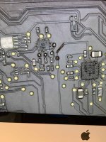
I also noticed the pad SPI_MISO_R completely burnt
The board dont work on bypass mode.
Thanks for your help")
On this board all the power rails for the PM_SLP_S4_L power supply are present but the CPU does not send the signal.
PPBUS_G3H 8,58V
PM_BATLOW_L 3,31V
SMC_RESET_L 3,39V
SMC_PM_G2_EN 3,42V
SMC_ONOFF_L 3,42V
PM_RSMRST_L 3,25V
PM_PWRBTN_L 3,41V
PCH_DSWVRMEN 3,3V
PCH_INTRUDER_L 3V
PCH_INTVRMEN 3,22V
PCH_SRTCRST_L 3,3V
RTC_RESET_L 3,3V
PM_SLP_S5_L = 0V
PM_SLP_S0_L = 0V
PM_SLP_SUS_L = 3,32V
With the multimeter I see a very small 0.5V pulse on the PM_SLP_SX when i short smc_onoff
This board has had repairs on:
- PPBUS_S5_HS_COMPUTING_ISNS
- CHGR_CSO_R_N
- CHGR_CSO_R_R
- SMC_TDI
- SMC_TDO
- SMC_TMS
- SMC_INT_L
I also noticed the pad SPI_MISO_R completely burnt
The board dont work on bypass mode.
Thanks for your help
")