
ytesfay80
Member
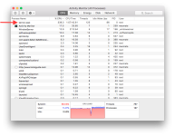
I got this board sent in from another shop. They said their customer had this fixed by someone in Hong Kong about 18 Months ago. It turns on but runs slow, the fans spin high and the system is being used at 88%. I ran ASD for this and I got an error on the Th1h sensor and this is what the hardware profile page showed.
Th1H Fin stack Error- SMC IO failed
reaing -124C
low-limit: 10C
High: 80C
Fin Stack Temp
Inspecting the board I see some very tiny spots of blue corrosion. I also saw a couple discolored points on the right side of the SMC but nothing much. I read through and followed this post from another similar issue but I still haven't been able to fix this. https://www.rossmanngroup.com/boards...5-running-slow
R5260-R5261 Diode Mode - Pin 1: 0.325v - Pin 2 - 0.52v
R5260-R5261 Voltage Mode - 3.33v on both sides
There is continuity from R5260/1 to U5511
Q5520 looks fine and the traces are good.
R5510/11/12 traces are good.
U5511 is getting the VDD power at 3.3v and 3.33v on Pins 9/10
The only issue I found was R5510/11 both have 3.3v on both sides of the resistor but R5512 has 3.3v on Pin 1 but Pin 2 is unstable. It will show close to 0v and every second or so it will very rapidly pulse and show something like 0.21v, 0.35v, 1.7v. I wasn't sure what could be pulling CPUTHMSNS_ALERT_L down so I replaced U5511 but it still does the same thing.
My last resort was going to be to remove the edge bonding from the SMC and put some heat and flux under there.
Attachments
Last edited: