820-00165 Green light, in S0 state, no fan spin

Neil250

Member
Green light on charger/ goes to orange.
No fan spin.
No liquid damage.

PP5V_S0: 4.95V
PP3V3_S0: 3.30 V
PP1V5_S0: 1.5 V

PP0V6_S0_DDRVTT: 0V at pin 1 C2700
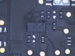
U7400
PIN 13 was 0.18V to ground in diode mode but ONLY 336 Ohms in Resistance mode
All the other pins (except ground pins of course) were in the kO range in resistance mode.

U7400
PIN 13: 1.2V

L7430: 1.2V pin 2

I assumed I was in S0 state.


Is there a short on PIN 13 U7400? It seems like very low resistance to ground and I'm not sure if
PP0V6_S0_DDRVTT should be 0 V


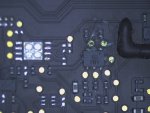
Q8150 also looks not good:
 

Attachments

  • Corrosion.jpg
    Corrosion.jpg
    294.1 KB · Views: 4
Last edited:

2informaticos

Administrator
Staff member
You can leave Q8150 out of board.
But shouldn't be the culprit, if ALL_SYS_PWRGD stays high.

Do you get VCORE?
MEMVTT_PWR_EN is required to enable PP0V6_S0_DDRVTT .
 

Neil250

Member
MEMVTT_PWR_EN :0V at pin 17 U7400

U1970 ----> NO SHORTS
6:1.20
4: 0 V so no output here ----> MEMVTT_PWR_EN

R1970:330 kO
1: 3.3 V
2: 0 V

CPU VCORE: R0860: 0 V
L7320: 0 V on pin 2

:-(

U7320

6: 5.09V
1: 0V
2: 4.78
3: 0
5: 0
7: 2.04

1: SHORT TO GROUND ON PIN 1 U7320

CPU_VCCST_PWRGD :0
ALL_SYS_PWRGD: 0.21
PP1V5_S0: 1.50 V
PP1V05_S0: 1.05 V
 
Last edited:

Neil250

Member
Post ohm value to ground at L7310/20----> 0.3 O

Do you have 3V at pin 7 of U1950? ----> 0 V

8: 3.43

1: 0.12
2: 3.33


U1950 does have corrosion at PIN 3 &4
 

Attachments

  • IMG_0014.jpg
    IMG_0014.jpg
    330.6 KB · Views: 3
Last edited:

2informaticos

Administrator
Staff member
Clean/change U1950.
If you get some S0 voltages, PM_SLP_S3_L is high.
Something pulls down ALL_SYS_PWRGD; can be U1950...
 

Neil250

Member
Good news, changed U1950.
Fan spin!!
But still no boot and still 0 volts on L7320

But it feels like progress with fan spin and PP0V6_S0_DDRVTT now has 0.6V
 

Neil250

Member
U1950 pin 8 looked burned
I cleaned it , pad was still there
replaced the chip

will check voltages
 
Last edited:

Neil250

Member
U1950

1: 3.33
2 3.33
3: 0.12
5:.90
6: 3.42
7: .66V

pLEASE note I soldered the U1950 on backwards at first, realized my mistake and fixed it
I even used a brand new U1950
That was my clumsiness

This is an AND gate so 5 & 7 have to be 3.42 V correct
1&2 are 3.33 so this chip is not outputting correctly on 7
 
Last edited:

Neil250

Member
OK now I am not getting anything on 1&2


I put a brand new U1950 in place

8: 3.42 V
7: 0

WTF?

I had fan spin before
even ALL_SYS_PWRGD is 0.1 V at pin 1

I thought i was close but this is bad I think

Maybe Q8150 is bad?
6:3.29V

nothing at pin 4 Q8150

How can U1950 work with no ALL_SYS_PWRGD

Q8150 must be bad?
but redundant?

looking at this post:

 
Last edited:

Neil250

Member
I soldered and resoldered U1950 5 times.
I even ordered a brand new chip and placed that there.

The ALL_SYS_PWRGD is missing which I assume is very bad if this board has any chance of starting.

Q8150 removal to see if it helps?

Should I go back to measuring all power rails again or maybe look at the generation of the
ALL_SYS_PWRGD signal. Maybe something is dragging it down.
 

2informaticos

Administrator
Staff member
At the same moment when PM_SLP_S3_BUF_L is high, ALL_SYS_PWRGD must appear too, if you remove any other component from its rail; apart of R8167, of course.
As I said, let Q8150 out of board and test again.
U1845, U1930 and SMC are connected there too.

Remove all, apart of R8167 and SMC.
 
Top