Hi again.
I have a 820-00165 that came in with a very small amount of water damage, but very little sign of corrosion.
Originally completely dead, but I found a tiny amount of corrosion on J9500, specifically around pin 19 SYS_ONEWIRE.
I cleaned and reflowed, then added some enamel wire and successfully fixed the onewire break...
I now have the Onewire LED on charger, but still no fan.
SMC reset changes LED colour from orange to green, then back to orange, correctly.
PPDCIN_G3H seems a bit low at 15.07, but is the same with two known good genuine chargers.
I also tried with another power daughterboard and flex cable that connects to J9500, with no change.
PPBUS_G3H, PPBUS_S5_HS_Computing_ISNS and PPBUS_S5_HS_OTHER_ISNS all 8.61v
PP3V42_G3H 3.42v
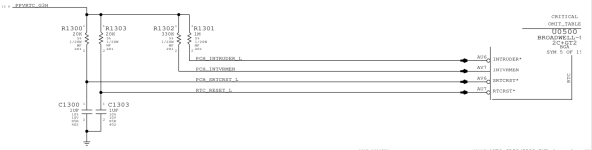
PPVRTC_G3H 3.34v
PP5V_S5 5.03v
PP3V3_S5 3.35
PM_BATLOW_L 3.3v
SMC_ADAPTER_EN 3.43v
PM_DSW_PWRGD 3.43v
PCH_DSWVRMEN 3.23v
PM_RSMRST_L 0v
PM_PWRBTN_L 1.01v
Any suggestions greatly appreciated.
I have a 820-00165 that came in with a very small amount of water damage, but very little sign of corrosion.
Originally completely dead, but I found a tiny amount of corrosion on J9500, specifically around pin 19 SYS_ONEWIRE.
I cleaned and reflowed, then added some enamel wire and successfully fixed the onewire break...
I now have the Onewire LED on charger, but still no fan.
SMC reset changes LED colour from orange to green, then back to orange, correctly.
PPDCIN_G3H seems a bit low at 15.07, but is the same with two known good genuine chargers.
I also tried with another power daughterboard and flex cable that connects to J9500, with no change.
PPBUS_G3H, PPBUS_S5_HS_Computing_ISNS and PPBUS_S5_HS_OTHER_ISNS all 8.61v
PP3V42_G3H 3.42v
PPVRTC_G3H 3.34v
PP5V_S5 5.03v
PP3V3_S5 3.35
PM_BATLOW_L 3.3v
SMC_ADAPTER_EN 3.43v
PM_DSW_PWRGD 3.43v
PCH_DSWVRMEN 3.23v
PM_RSMRST_L 0v
PM_PWRBTN_L 1.01v
Any suggestions greatly appreciated.
Last edited: