820-01700 A2141 ppbus 12,3v

Bravo2001

Member
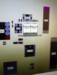
Hi have a weird problem, Received liquid damaged a2141 16" the two left USB-C ports stay on 5v, 0,330A Upper on steady lower boot loops. The right ones go to 20v 0,107A both steady. When connected to either 4 USB_C PPBUS_G3H goes to 12,3V. Also received with a solder blob below F7001 connecting 20v to a test probe below it which is not in the schematic. See attached picture.
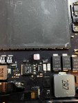
IMG_1736.jpegIMG_1737.jpeg

After removing the solder joint the test probe measures 5V But can not lead it anywhere... Is the the rabbithole...

Also replaced both CD3217 on the left side with donor cd3217 which I reballed myself (I'm skeptical if I reballed them good) But after putting them back gave exact the same measurement as before. So nothing changed. Please help.

Measuerments:

PPBUS-G3H 12,3V
PP3V3_G3H 3,3V

THXS
 

2informaticos

Administrator
Staff member
Compare diode mode readings around CD3217 chips, between left/right channels.
You need to get 01700 board and check if that is just a test pad, or broken trace.
 

Bravo2001

Member
Hi, checked diode mode readings around CD3217 chips left en right Found an OL on Pin79 UB300 USBC-TA-SBU1 on the left. On the right it was 0.625. So changed the CD3217 which I ordered new. Now boft sides give same results. But still 5v on left side and 20v on right side.

PPBUS_g3h is 12,3v that should be 12,6v right?

What can I Check more?
 

2informaticos

Administrator
Staff member
Yeah, 12.3V is incorrect voltage; no good communication between T2 and CD3217 chips.

Something more affected by liquid spill.
Inspect UB090 surrounding resistors and its traces.
 

Bravo2001

Member
Inspect UB090 surrounding resistors and its traces.

You where RIGHT again... It was RB281 which had a different diode mode measurement than corresponding measurement on right channel. Now all 4 ports give 20v 0.1a. But still getting 12.3v on ppbus.

Tried to get in DFU mode to restore t2... But can't get it in DFU mode. (I know how, done it a bunch of times) Could It be that keyboard not working? Is there a way to to without keyboard.

What more tips can you give me, You are spot on every time! This
 

2informaticos

Administrator
Staff member
Remember that this machine requires 96W charger to boot; if no good battery connected.

You can use SWK003 pads, instead of keyboard; to force DFU mode.
 

Bravo2001

Member
Hi Thxs for the fast reply.

I know about the charger. I always use the 96W charger...
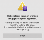
Got to force DFU mode but came back with error. Schermafbeelding 2022-04-04 om 17.11.33.png

It feels like I'm olmost there...please advice further.
 

Bravo2001

Member
Did not check, was assuming that first we had to have ppbus_g3h before anything else. Will check for ssd voltages.
 

Bravo2001

Member
Do you get all SSD voltages?

PP3V3_G3H_SSD0_SNS 3,3V
PP3V3_G3H_SSD1_SNS 3,3V
PPBUS_G3H_SSD0_SNS 12,3V
PPBUS_G3H_SSD1_SNS 12,3V
PP2V5_NAND_SSD0 0V 56ohm to ground
PP2V5_NAND_SSD1 0V 56ohm to ground

PP1v8_g3s 0v
PP5v_g3s 0v
pp3v3_g3s_t 0v

Is there a short in de Nand? Had that ones before and was unfixable...
 

2informaticos

Administrator
Staff member
"L9080/81 424"
Diode mode reading from good board.
You should get a value in the same range.
You can't get exact same reading, but 56 ohm is really bad; points to damaged NAND.
 

2informaticos

Administrator
Staff member
Is normal; allow some time to discharge the remanent voltage.
Also disconnect the battery, before measuring in diode mode.

L9080/81 look good.
Do you get similar reading at L9580/81?
BTW, good enough to check one coil, when more connected together.
 

Bravo2001

Member
Hi 2 informaticos, Back after a long while again with this board.
L9580/81 are same reading 372.

I was checking booting sequence and all the rails are ok until I get to P5VG3S_EN That one is missing... Looks like the PMU does not send Enable signal. Should I further investigate there?

Thxs again
 
Top