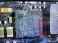
Hello , first of all I'd like to say that this is my firt board level repair so please be patient if I get things wrong (like I forget to specify important details), I'll try my best. I've got a 820-02098 board which is liquid damaged. Firt of all after removing the board i checked for liquid damage and I cleaned it as much as i could with IPA, but averall the board looked pretty good (no visibly broken componets, no blacked-out areas). I then moved to check if the capacitors with the most oxidation where shorted out but I couldn't find any. Luckily I got my hands on the schematics (https://www.badcaps.net/forum/showthread.php?t=110182&highlight=m1+pro+schematic), with that plus the repair wiki i found out that my 3.8V line is working properly (or at least I read 3.8V according to the repair wiki). The problem comes with the PP5v_S2_MAIN line, indeed I don't get any voltage (measured from the inductor indicated in trw), so I moved to the boardview and found that that inductor is connected to 3 pads of the adiacent chip (the one in the image, the pads highlighted). My issue is that that area wasn't damaged at all by liquid (at least not visibly) so I don't know why the problem could be there, but also it looks like the pads aren't properly soldered. I decided to try and desolder it using aboundant flux and a hot-air station. At first I set it to 200C but couldn't get anything moving so I moved gradually to 300C until I decided to stop because I didn't want to cause any damage. My questions are: could this chip be the problem or maybe the absence of PP5v_S2_MAIN is determined by some other component I couldn't locate? If so how can remove it properly?

-
For $29/mo, we provide access to advanced level technicians who will answer your questions on any Macbook board related matter to the best of their knowledge promptly & walk you through how to solve your problem so you can deliver a working board to your customer.Subscribe Now
You are using an out of date browser. It may not display this or other websites correctly.
You should upgrade or use an alternative browser.
You should upgrade or use an alternative browser.
820-02098 water damage, no PP5v_S2_MAIN
- Thread starter devoniodd
- Start date
First of all, welcome to the forum!
Keep in mind, the temp set on the hot air station, is not the expected temp on the board.
You will probably need to set 400-450 degrees on the hot air station.
Also need to adjust air flow properly; practice on scrap boards.
When you deal with a power supply controller, check first if the chip gets correct voltage on its power pins; 10-12 in this case.
It also need an enable signal, P5VS2TPS_PWR_EN.
Do you get other voltages on U7700 and U8100?
What about 3V3_S2 and 1V2_S2?
Is the machine recognized in DFU mode?
Thanks for the reply! So, I am not really sure on where to measure voltage for both U7700 and U8100 (although they do not have any visible liquid impact). Regarding the power supply controller I get 12V on the power pins and nothing (sometimes it briefly jumps) on the enable pin. Rails 3V3_S2 and 1V2_S2 seems to be down (I wasn't sure where to check so I just looked in the boardview for resistors and capacitors connected to that line). I am not sure about DFU, I will check as soon as I get it together, but I know the magsafe charger is not lighting up and the battery contacs show 164mA.
Lot of small coils around U7700 and U8100.
Some of them must get voltage, in order to enter DFU.
Be aware, many coils are tied together.
Use the common output pin of one coil to check; don't waste time measuring on each common coil.
Both chips have also several LDO voltages to check; look at pages 37 & 41.
Some of them must get voltage, in order to enter DFU.
Be aware, many coils are tied together.
Use the common output pin of one coil to check; don't waste time measuring on each common coil.
Both chips have also several LDO voltages to check; look at pages 37 & 41.
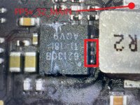
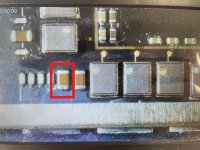
Not sure what you are referring to with pages 36, 41. Anyway I measured both U7700 and U8100 but it looks like there is no voltage. I noticed that when measuring U7700 using a cap (C80F2, see image) a little smoke comes out and the tester probes ""sticks"" to it, not sure how to diagnose that...
Attachments
Page 37 and 41 of schematic, show you the LDO voltages of mentioned chips: LDOS blocks on the bottom.
On the left side you can see the input voltage of any LDO (output on the right).
If an input voltage is not present, output LDO will not be present, of course.
Any LDO generated from 3V8_AON, must be present.
U7700 and U8100 have also many buck controllers, which also must work before the board starts.
You should check which voltage is generated, or not.
In case not, check for short there.
Thnaks for the explanation, I just checked and the 3V8 line is present, but others (1V8 and 1V2) are not, knowing that where should I look for shorts? Should I look for where 1V2 and 1V8 is generated, if so is there a specif place in the motherboard for that or maybe components I should look for?
Any point of a missing voltage rail is good to check.
I hope you can find one with easy access.
Don't make any short more with multimeter probes; get ones with fine tips.
1V8_S2 comes out from L7830.
1V2_S2 comes out from L8280.
All S2 and AWAKE voltages must be present, to assist M1 in power on sequence.
As you get 3V8_AON, check if Master (U8100) LDOs derivated from 3V8_AON are present (page 41).
I measured 1V8_s2 and 1V2s2 from the connected caps next to them (could not get the probes to the inductors themselves) and it looks like they are shorted out, GND is connected to both 1V8_s2 and 1V2s2. Regarding output from PP3V3_S2 LDOs in U8100 I tested them by looking at resistors that should be on the same line, but no voltage (i.e. I measured 30mV in CF231 that should be connected to PP3V3_S2)
Post the exact resistance to ground on the shorted lines.
Before measuring resistance, or diode mode, allow 10-15s after removing the charger/battery.
Before measuring resistance, or diode mode, allow 10-15s after removing the charger/battery.
I asked about resistance (ohm scale), not diode mode.
I suppose your readings are in ohm indeed; 1.2 in diode mode, can't beep.
These values look like pure short.
Remove R/L8280 and check where the short remains.
Do the same with R/L7830.
I suppose your readings are in ohm indeed; 1.2 in diode mode, can't beep.
These values look like pure short.
Remove R/L8280 and check where the short remains.
Do the same with R/L7830.
Do you get voltage on any mentioned LDOs?
U8100 starts first, as its LDOs (almost all) are generated from 3V8_AON; only its VLDO5 comes from 1V2_S2.
U8100 starts first, as its LDOs (almost all) are generated from 3V8_AON; only its VLDO5 comes from 1V2_S2.
"I get a short to ground with a jumping value of resistance only when the power is plugged."
NEVER again check resistance, or diode mode with power applied!!!
"Before measuring resistance, or diode mode, allow 10-15s after removing the charger/battery."
Wasn't this clear enough???
Looks like have a bad U8100.
Good luck to find a replacement.
NEVER again check resistance, or diode mode with power applied!!!
"Before measuring resistance, or diode mode, allow 10-15s after removing the charger/battery."
Wasn't this clear enough???
Looks like have a bad U8100.
Good luck to find a replacement.
U8100 could got damaged after that short, but we don't know which voltages have been present before.
Maybe it was bad already.
PMIC is not "married" with M1, but not sure if serves one from different board model.
As per note on the top of page 43, some pins are platform dependant...
Maybe it was bad already.
PMIC is not "married" with M1, but not sure if serves one from different board model.
As per note on the top of page 43, some pins are platform dependant...
3V3_AON is there?
You should change U8100.
Just in case, check diode mode on all its coils.
Do the same for U7700.
You should change U8100.
Just in case, check diode mode on all its coils.
Do the same for U7700.