For $29/mo, we provide access to advanced level technicians who will answer your questions on any Macbook board related matter to the best of their knowledge promptly & walk you through how to solve your problem so you can deliver a working board to your customer.
Wait hold on I feel like im missing something here. PPBUS_G3H never fluctuated at any point. Even in the beginning before removing any components, PPBUS_G3H was stable at 12.5V (post #1).
Ok so with the multimeter, which doesn't really update very quickly, it looks around 12.6V on Pin23, though the number moves around a little bit. This is similar to the DC voltage randomly jumping from 0V -> 2.3V -> 0.7V -> 0.2V -> etc etc for pulsing pins.
So based on what you said earlier about the U7000 and SMC, are you suggesting the next thing to do is to replace both components or something? The last concrete step was to remove the fuses.
In an earlier post, you've said to get steady 3V at SMC_PM_G2_EN, if press SMC_ONOFF_L for 3s.
Is that still true?
If yes, check if 3V3_S5 gets steady at same time.
I am super confused what is going on now because the pulsing frequency has now changed to what looks like 0.2Hz.
So what you stated is true, if I press SMC_ONOFF_L for about 1s (3s would be the same), SMC_PM_G2_EN gets solid 3.5V. 3V3_S5 gets solid 2.1V. 3V3_S5 doesn't look right only having 2.1V...
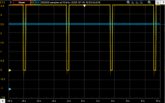
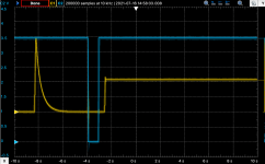
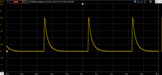
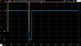
I have attached 3 images. SMC_ONOFF_L is the blue line in the images, while the yellow is the tested pin.
3V3_S5.png - data capture after a power cycle, and then pressing the SMC_ONOFF_L
SMC_PM_G2_EN.png - after a power cycle, and then pressing the SMC_ONOFF_L
3V3_S5_POWERCYCLE.png - 3V3_S5 immediately after MagSafe power cycle, no SMC_ONOFF_L triggering
SMC_PM_G2_EN_POWERCYCLE.png - SMC_PM_G2_EN immediately after MagSafe power cycle, no SMC_ONOFF_L triggering
Please, let o-scope aside; do not complicate the job more than needed.
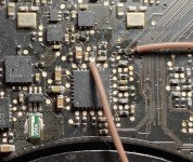
Post U7201 voltages, when you get steady SMC_PM_G2_EN; pins 23, 12, 13, 22, 29, 21.
If you don't get correct 3V3_S5 in that case, there's something wrong in U7201 area.
Inspect all surrounding resistors and traces; pay atention to R7260/61, R7263 and C7264.