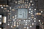
820-3115-B - Need to hold down power button to turn on

Antonio

New member
First post on this forum, so excuse me if I leave something important out. Checked a bunch of other posts and didn't see anything related to this, so....

I have a mid 2012 board that only turns on if you hold the power button down. I'll get a small fan spin from a click, but in order to get it to do anything more I have to hold it down till it's nearly completely booted. I can boot off battery and the power cord both individually, and together. Being plugged in without the battery in results in me having to hold the power through the 5 light "where's your battery" thing, as well as the rest of the boot.
After it actually boots, it works, but EXTREMELY slowly.
As far as i'm aware nothing has been spilled on this computer, but I did get it off eBay, so, something was probably spilled on it...

I ran the ASD and it failed at IPBR

Sensor - Current (IPBR) -- Charger BMON (Prod) (test 1) - Sensor Range Reads Within Operating Range
- Check to ensure sensor reads within operating range.
ERROR - Sensor is reading above the high limit
- T E S T F A I L E D -


Andddd that's about where I got to.

I've already ran the board through an ultrasonic cleaning, but other than that i'm pretty much lost. My initial thought was that I wasn't getting ENOUGH voltage considering it was running so slow, but I'm new to this so everything I think is wrong anyway. Oh well.


Anyone have any tips? I do have all the tools required to do any of the repairs, along with donor boards for parts, but I don't have a schematic or board viewing software yet, so any components you mention if you coulda sorta just... "this thing, it's in the top like 2 inches of the board", that'd help me greatly. I should be able to figure out where everything is if I have a general idea of where the component is.

Thanks in advance!
 

aprendiz

Moderator
Check sense resistors R7050, R7051 and R7052, make sure that all traces that connect this components with ISL are ok...
 

Antonio

New member
Oh, woah, I don't know how I completely missed that area. There's about 6 corroded pads and a few resistors around there that are all sketchy looking. Thanks for the help! Not gonna be able to attempt to fix it tonight, but nice to know I at least have a place to look now haha.
 

larossmann

Administrator
Staff member
My bet is the ISL sent 16v to the SMC. fix up all the corroded shit before you touch the SMC, but SMC is my bet here.

As much as I like to blame R7050/R7051/R7052 disconnects for quarter fan spin, it wouldn't be this intermittent. What you're describing is classic SMC fuckup on an A1278 board.
 

Antonio

New member
No Title

Yeah, the whole area is just kinda shit in general. Is this SMC the same specs on an older board? I have lots of 2010-2009 ones I can take things from, but unfortunately this is the only one of this exact type I have left.
 

Attachments

  • photo171.jpg
    photo171.jpg
    127.8 KB · Views: 0

Antonio

New member
measure resistance between pins 17/18 and pins 27/28 of U7000 so we can rule that out.

I didn't manage to get a reading before replacing it, but I swapped out "one" of the shit resistors at the top of my picture (not near my computer with the schematic to tell me which one it was called), and now it's acting differently.

Previously it was having trouble all the time, but now I can actually run it completely fine while it's plugged in. The 100% CPU usage is gone, but the long start up hold is still required. The catch to this is that it will only work if the battery is unplugged. I still get the same trouble while the battery is attached (regardless whether it's plugged in to the charger or not as well), but nothing caught on fire, so I guess we'll consider it neutral...

Anyway, i'm not able to get back to the computer with all my helpful doodads to show me what i'm doing in any way till tomorrow, but with the new situation does that still sound like measuring there would be of any help? I've felt around the area (with the battery plugged in, and on wall power alone) and nothing seems to be getting hot anywhere near there, but I did notice a high pitched sound coming from the area slightly above the battery connector. The sound is only there when the battery is plugged in. Besides all the crap near U7000 nothing else on the board looks off at all, especially in the area the whine is coming from. I have no clue if this helped narrow down the problem or just made it even bigger, but if anything, at least I can use it without a battery now!
 

Crizz

Member
Defenetly check the resistance between these legs Louis mentioned before and tell us the value.
I would change the ISL straight away to be sure there is no corrosion underneath it since the area looks like C&B ;)
 

Antonio

New member
Replaced r7051 and r7052. Measured 13-14ish ohms from pins 17 and 18. I'm not 100% sure if that's accurate since the tips of my multimeter are shit, so i'm not going to attempt measuring the other set until I figure something out or get the tip extender things.

What should I be getting from 17-18 on u7000? After replacing those two resistors the computer is turning on (thank god), but it's still having the same problem, so that pretty much rules that out :/
 

Antonio

New member
I get 3.3 ohm when I measure at each end of c7050. Pins 17 and 18 wind up going there, so I figured it'd be easier to get my shitty multimeter to touch that than the pins themselves. I'm pretty new to this, so if that's just the resistance of c7050 itself and not what the SMC would be getting, feel free to make sure I know i'm stupid so I can learn lol.

I'll try to figure out something to measure at the pins tomorrow.
 

george-a

Member
(sorry for jumping your thread Antonio - question opportunity!!!) Louis could you also explain how can ISL send 16V to SMC? And how can we test if that happened?
 

aprendiz

Moderator
Antonio check if there is continuity from pin 1 of R7051 to pin 18 of ISL and same for R7052 to pin 17, could be a broken trace...

george-a ISL does not send that voltage to SMC, otherwhise SMC would be fried..... ISL read sense resistors and report the results to SMC through I2C ( SMBUS_CHGR_SCL and SMBUS_CHGR_CKL pins )
 

Antonio

New member
I can't seem to get good contact with any of the pins on U7000. There's a bunch of sticky leftover flux crap that I can't seem to get out of this area, which is blocking me from making sold enough contact with anything to measure properly through. Any tips to clean it up? Q tips just rip apart and leave me with an even messier area, so i'm not gonna try that again :p
 

Antonio

New member
I guess I just wasn't using enough alcohol last time. Cleaned it up a bit and now I can get a better reading.

It "seems" like pins 17 and 18 are bridged. Not getting continuity from pin 1 of r7051 and pin 18, or even the little dot above it, so that trace may be broken on top of 17 and 18 being bridged. Gonna try to fix all that and see what happens!
 

Antonio

New member
FIXED IT!

No 100% CPU usage, turns on right away, runs off battery, ect.

The problem was the broken trace. I just kinda swiped over all the pins on that side to get em separated then tried my best to get some solder down to that other pad pin 18 connects to.

Plugged it in and it turned right on! Gonna run ASD on it to make sure this wasn't the only problem though.


Anyway, thank you guys all so much for your help! This is the first board i've ever successfully repaired. Literally never thought i'd get to the point I could do this. I'll make sure to update everyone if my house starts on fire after leaving the computer alone for a bit.
 
Top