A1229 Voltages and Magsafe

cptnzod

New member
Folks, I just joined the group. Just a hobbyist. Bought a non-working 2007 17" Macbook Pro. Very nice and not working :) Will attempt to repair.
I had green light. Took out the motherboard and no green light now. a few questions if you could please answer.
1- Does the Magsafe charger has a right way to plug in? Its not keyed so can be plugged in any which way!
2- What are the voltage levels on the Charger?
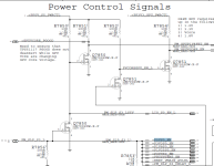
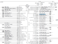
3- This board A1229 820-2132 is supposed to have 18.5v in PPBUS_G3H. I measure 16.5v. Does this mean the Magsafe is inadequate? If so can I test with 18.5 Power Injection?
4- Have purchased a boardview file for this from appleschematics.com. I also have a PDF with matching numbers. There are transistors in both which are not present on the board. There is not even a place for it. It was not taken out. Just wondering if I have the right boardview file. How do I know I have the correct boardview file and where do I get just the one I need? Don't want to buy the whole pack just yet.
5- Louis does not have tutoring anymore. Is there any place which does?

Thanks in advance for your attention.
 

piernov

Moderator
Staff member
Be aware that this will have a dead GPU in any case. Also it's easy to have bad contact in the Magsafe port with old machines, and in the FFC connector between LIO board and logic board.
1/ Magsafe can be plugged in both ways. If you don't have at least some experience with these machines I'd not recommend trying to jump straight into board repair.
2/ It depends on the Magsafe. This board requires a Magsafe1 85W which can send out 18.5V but it can also decrease the voltage a little bit when idling, and it'll only send out 6V when not connected to the machine.
3/ PPBUS_G3H should be somewhere around 12.6V as usual.
4/ No sure why you'd pay for schematics/boardviews when they're available for free.
Like every logic boards, some components will not be populated because they're not necessary on production boards. They're annotated with NO STUFF or a BOM option that's not listed for production in the BOM option table.
5/ I'd recommend watching Louis Rossmann videos as most of the information is readily available in them. There's also his repair guide and his wiki as well as other sources of information such as https://logi.wiki/ , badcaps.net and this forum.
 

2informaticos

Administrator
Staff member
First of all, welcome to the forum!

You can try to solve the power problem for this machine, but as already mentioned, this board could have bad GPU; so be aware of that.

"is supposed to have 18.5v in PPBUS_G3H. I measure 16.5v"
Only possible if Q7901 is shorted.
Change it and also check R/C7903 and D7900; may need to change U7900 too.

About Magsafe light, which is the code of your LIO board?
Many times LM397 gets burnt there, but could be other thing.
 

cptnzod

New member
Thanks for your response.
Here is what I have:
Power Board
820-2140-A

Q7901:
PIN VOLTAGE
5 16.26
1,2,3 12.69
4 13.43

D7900:
1 5.08
2 17.38

I have all pics attached.
I have done more testing and tracing. Kind of fun until I get to the end and hit a block:

Missing PPVCORE_S0_CPU_REG which points to U7100
VDD is missing in U7100
Which depends on PP5V_S0_CPU_IMVP
PP5V_S0_CPU_IMVP depends on PP5V_S0_FET
PP5_S0_FET depends on PP5V_S0P5VS0FET and P5VS0_EN
Got 5 volts on the first and 0 on P5VS0_EN
P5VS0_EN comes from PM_SLP_S3_L
PM_SLP_S3_L comes from ICHM8M U2300

I have all pics attached.
What is this chip?
How do I go forward from here?
 

Attachments

  • 0-PPVCORE_S0_CPU_REG.PNG
    0-PPVCORE_S0_CPU_REG.PNG
    85.2 KB · Views: 1
  • 1-u7100.png
    1-u7100.png
    170.2 KB · Views: 1
  • 2-pp5v_s0_cpu_imvp.png
    2-pp5v_s0_cpu_imvp.png
    19.3 KB · Views: 1
  • 3-pp5v_s0_fet.png
    3-pp5v_s0_fet.png
    23.8 KB · Views: 1
  • 4-p5vs0_en.png
    4-p5vs0_en.png
    66.4 KB · Views: 1
  • 5-pm_slp_s3_l.png
    5-pm_slp_s3_l.png
    166.2 KB · Views: 1

2informaticos

Administrator
Staff member
U2300 is the Intel sothbridge chip.

Please post accurate and actual measurments.
You've said to have 16.5V at PPBUS_G3H; which is same at L7900 and pins 1-3 of Q7900.
12.6V is good voltage there; do not waste time around U7900, if you get this voltage.

How do you get 5V_S0_FET, with 0V at 5VS0_EN???
Is Q7020 shorted I/O?

"VDD is missing in U7100"
Check diode mode to ground there.
Is R7112 burnt?
Do you get PVCC?
 

cptnzod

New member
Sorry for inaccuracy.

I have measured again and very accurately and its been fun.

PPBUS_G3H 12.65v checked at L7900

Missing PPVCORE_S0_CPU_REG, and no screen, no chime...

On Q7100 pin 5 I have 12.65 ( PPBUS_G3H )

On U7100 pins 34 and 35 are Zero and both sides of R7112 are Zero and R7112 is 10 Ohms

On U7100 VDD is missing. Ohmmeter test to ground is 16.89Kh ( red probe on ground). Pin 22 is Zero, VDD depends on PP5V_S0_CPU_IMVP and this depends on PP5V_S0_FET

PP5V_S0_FET Comes from Q7020

On Q7020, there is 4.97v on PP5V_S0_P5VS0FET at pin7, 3.38v on PP5V_S0_FET at pins1,5,8, I have 4.94v on pin4

The question is why we have 3.38v instead of 5v!

Checking around Q7020 I see Q7002

On Q7002 ( confusing data between boardview and Schematics on which pin is which )

pin 6 is 4.96v ( used for other circuit )

pin 3 is 4.96v

pin 5 is zero

All other pins are zero


Pin 5 which is Gate comes from P5VS0_EN which comes from PM_SLP_S3_L

PM_SLP_S3_L comes from ICH8M/U2300


Where to go from here?
 

2informaticos

Administrator
Staff member
So you are searching for CPU vcore before geting the voltages from pages 62-64?
You can't get S0 voltage before S3.

Do you say PM_SLP_S3_L is not prresent?
What about PM_SLP_S4_L?

Take a look at Power On Sequence List from page 3.
 

cptnzod

New member
Thanks for the hints. I followed your suggestions as per below.
PPBUS_G3H 12.65V

PPDCIN_G3H 16V

PP3V42_G3H 3.42V

PP5V_S5 4.97V

PP5V_S3 25mV

Moving to Q7000 to find PP5V_S3

Pin 4 has 4.97v

Pin 3 has 4.94v

Moving to Q7012 to see if it opens to ground

Pin 6 has 4.96v

Pin 2 has ZERO which comes in from P5VS3_EN

This leads to PM_S4_STATE_L which comes from ICH8M/U2300


Where to go from here?
 

2informaticos

Administrator
Staff member
You didn't really post exact level for PM_SLP_S4/3_L signals.
Check for pulse at least; triggering SMC_ONOFF_L to ground (temporary contact only).

Southbridge requires some other signals (reset, RTC?), to start power on sequence.
 

cptnzod

New member
I am not quite sure what I should check. Where to check for PM_SLP_S4/3?
Where do I check for those 2? At ICH8M? That has lots of pins and not exposed. So not sure how to check that.
I followed the diagram and went forward from G3H and S5 and did not run into those 2 above to test.
To answer SMC_ONOFF_L is 3.4v. Checked that on J9600 pin 5.
If you could please state what I should check next. Appreciate.
 

2informaticos

Administrator
Staff member
Trigger SMC_ONOFF_L and check for pulse at PM_SLP_S4/3_L.
Use boardview, you will find points where to test them.
 

cptnzod

New member
On baordview I can find PM_SLP_S3_L on Q7051 and its zero at the moment. cannot find S4_L
Forgive me but how do I trigger SMC_ONOFF? And what will that tell me?
 

2informaticos

Administrator
Staff member
Use R5015 pads, instead of power button.
When pressing power button, PM_SLP_S4/3_L both must pulse, at least.
If not, check for drop pulse at PM_PWRBTN_L at same time.
PM_RSMRST_L must be steady high.
 

cptnzod

New member
I am guessing you mean to short the pads which does the same as power button.
Shorted the pads together, PM_SLP_S3_L was dead zero.
Could not find a test point for PM_PWRBTN_L accessible. Under U4900 pin 45 and no test point.
PM_RSMRST_L is steady 3.39
 

2informaticos

Administrator
Staff member
"short the pads which does the same as power button"
Only temporar contact, like prressing power button.
Do not keep the pads shorted.

Check RTC signals of U2300.
 

cptnzod

New member
I did it as you mentioned.
PM_SLP_S3_L was dead zero
I checked across R2811 for the RTC
SB_RTC_X1 300mV
SB_RTC_X2 227mV
 

2informaticos

Administrator
Staff member
Reading your posts, I was thinking you want to learn.
We have lot of information on the forum.
We discussed many-many times about what we understand as RTC signals.
I didn't mention RTC clock, what you've checked.

Please, post SB_RTC_RST_L, SB_SM_INTRUDER_L, SB_INTVRMEN and SB_LAN100_SLP.
As you can see in page 23, all go to southbridge RTC block.

Be aware, this old board can already have a dead GPU.
It may worth the time only for training.

The forum goal is to help the members in a repair process.
If you are interested in training, contact Rossmann staff.
This may depend on your location.
I can tell you that reading the forum you can learn a lot of things.
Apart of solutions, we have theory posted too.
 

cptnzod

New member
Would love to get training. They state no more training on their site. I am on the West Coast far away from NY. Will call them and try.
I will look at other parts of the Forum. The videos from Louis do not discuss what you are asking here. They discuss mostly the power rails. If this problem were just power rails I would have gotten it by now. Would be nice to see what the problem is here.
Here are the measurements you asked:
SB_RTC_RST_L 3.29V
SB_SM_INTRUDER_L 3.0V
SB_INTVRMEN 3.2V
SB_LAN100_SLP 3.2V
 

2informaticos

Administrator
Staff member
Do you get steady voltage at L7320/60?

Do you have schematic/boardview for LIO board?
Still missing Magsafe light?
 
Top