
-
For $29/mo, we provide access to advanced level technicians who will answer your questions on any Macbook board related matter to the best of their knowledge promptly & walk you through how to solve your problem so you can deliver a working board to your customer.Subscribe Now
You are using an out of date browser. It may not display this or other websites correctly.
You should upgrade or use an alternative browser.
You should upgrade or use an alternative browser.
a1502 820-4924-A Liquid Damage... no image, but boots when Magsafe plugged in
- Thread starter papalati
- Start date
Image should appear first.
To avoid any artifact, or improper image on the display, the backlight appears with a small delay.
Do the mentioned tests about internal LCD output...
"When you start the board with internal LCD connected, check for voltage at R8320 pads.
You should also get voltage there in the first few seconds at least, even without LCD.
Keep the multimeter probe connected there when turn on the board; especially when hear the chime"
papalati
Member
Voltage is stable on pad 1. Voltage starts stable on pad 2 then fluctuates for a 2-3 seconds then becomes stable again and stays at 5v. Happens exact same way every boot.
LCD is too cracked to see any image. Even when good board is in the only thing I can see is just 2-3 cracks of light can't even see the little folder with question mark.
On D7710 - Pin 2 is .005 and Pin 1 is .023 while internal lcd is connected. That is no good I'm assuming.
LCD is too cracked to see any image. Even when good board is in the only thing I can see is just 2-3 cracks of light can't even see the little folder with question mark.
On D7710 - Pin 2 is .005 and Pin 1 is .023 while internal lcd is connected. That is no good I'm assuming.
"On D7710 - Pin 2 is .005 and Pin 1 is .023"
Diode mode to ground?
I hope you've disconnected power first.
BTW, I was asking for voltage at D7710...
Diode mode to ground?
I hope you've disconnected power first.
BTW, I was asking for voltage at D7710...
papalati
Member
"On D7710 - Pin 2 is .005 and Pin 1 is .023"
Diode mode to ground?
I hope you've disconnected power first.
BTW, I was asking for voltage at D7710...
That was voltage at d7710. Power was connected.

I thought you wanted it to be powered on since we just checked voltage on r8320 with power on. Sorry.
Pin2 was .005 volts and pin1 was .023 volts. NOT diode mode. That's why I was assuming it was bad since not that many volts were showing on ppvin and out.
Correct, I wanted voltage, but your values look more than diode mode; 3 decimals used for that usually.
For voltage, you could write just 0V, no differenece.
BKLT_EN_R still not posted.
Please, do note quote an entire post visible few centimeters above...
For voltage, you could write just 0V, no differenece.
BKLT_EN_R still not posted.
Please, do note quote an entire post visible few centimeters above...
papalati
Member
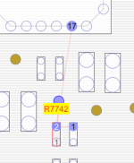
BKLT_EN_R at R7742 is 100.7
BKLT_EN_R at C7742 is 100.7
BKLT_EN_R at Pin 17 on u7700 is 100.7
I no longer have the good board, so I was not able to compare, should there be a component at C7742? Cause it is just an empty pad? I attached best pic I could get. I thought R was for resistor and C for capacitor, but there is no capacitor at C7742 I can see.
Attachments
All the components marked as "NO STUFF", are not present on the board.
Need the voltage at BKLT_EN_R; one point is sufficient...
Need the voltage at BKLT_EN_R; one point is sufficient...
So enable is present, lets check adjust somehow.
Post diode mode and voltage at BKLT_SCL/SDA lines.
Also post voltage for BKLT_SD.
Post diode mode and voltage at BKLT_SCL/SDA lines.
Also post voltage for BKLT_SD.
With 0V on BKLT_SD, you should have voltage on D7710; post both pins voltage.
OK, then post Q7700 voltages.
Remember to keep internal LCD connected.
Also check F7700...
Remember to keep internal LCD connected.
Also check F7700...
"BKLT_SD = 0v"
If this is correct, you should have 5V aprox on pin 3/Q7700.
Check R7701/02; measured onboard, ohm scale.
If this is correct, you should have 5V aprox on pin 3/Q7700.
Check R7701/02; measured onboard, ohm scale.