(347) 552-2258
[email protected]
-
For $29/mo, we provide access to advanced level technicians who will answer your questions on any Macbook board related matter to the best of their knowledge promptly & walk you through how to solve your problem so you can deliver a working board to your customer.Subscribe Now
You are using an out of date browser. It may not display this or other websites correctly.
You should upgrade or use an alternative browser.
You should upgrade or use an alternative browser.
a1502 820-4924-A Liquid Damage... no image, but boots when Magsafe plugged in
- Thread starter papalati
- Start date
Resistors look good.
Do you really have 0V at pin 2/R7702?
Do you really have 0V at pin 2/R7702?
papalati
Member
Okay, so I wanna clear something up... you asked previously "When you start the board with internal LCD connected, check for voltage at R8320 pads."
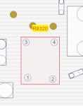
Boardview shows R8320 as a 4 pin pad as I took a screenshot of, but when I look at the board it looks like pins 1 and 2 are a bridged pad to 3 and 4. Unless the 2 tiny pads above them are 3 and 4.
Please see comparison pics and let me know which letter is right. A or B.
I'm assuming A is right.
Boardview shows R8320 as a 4 pin pad as I took a screenshot of, but when I look at the board it looks like pins 1 and 2 are a bridged pad to 3 and 4. Unless the 2 tiny pads above them are 3 and 4.
Please see comparison pics and let me know which letter is right. A or B.
I'm assuming A is right.
Attachments
R8320 is not placed on the board, so all 4 pads are tied together; for this reason I said "pads", not "pins".
No reason to replace Q7700, if BKLT_SD is not 0V.
Try known good full LCD assembly; must be from 2015.
No reason to replace Q7700, if BKLT_SD is not 0V.
Try known good full LCD assembly; must be from 2015.
papalati
Member
So what are the two small points above the pads that I marked 3 and 4 in image A?
Cause I don't have another panel to try. If I got the board working then I would've spent the money on another panel but if I can't get the board working then I'm not spending 300-400 on a good panel.
When I connected the good board before sending it back it showed the backlight and this one doesn't still so that means something is still wrong with this one.
I think I have to give up then at this point.
If you get 3V at DP_INT_HPD, internal LCD is detected and probably the image is there; but not visible on the cracked screen.
Until BKLT_SD gets 0V, you cannot get any voltage at D7710.
Do you still have 3V at BKLT_EN_R?
If you got backlight with another 4924 board on this LCD, then the problem is in the actual board.
"So what are the two small points above the pads that I marked 3 and 4 in image A?"
Are the pads for Kelvin connection lines of Isense, not used in this case; directly connected to pins 1 & 2 respectively.
Post all voltages for U8300/10/30.
Please pay more atention wgen you work.
We need to be sure about all posted values.
Pins 1 & 3 of U8300 are tied together, like in schematic.
Do you really have 0V at all U8310 connections?
Pin 1/A1 is connected directly to 3V3_S0 (C8308)....
We need to be sure about all posted values.
Pins 1 & 3 of U8300 are tied together, like in schematic.
Do you really have 0V at all U8310 connections?
Pin 1/A1 is connected directly to 3V3_S0 (C8308)....
Why try to make contact underneatch the chip?
Even on bigger QFN chips, you can easy make a short between pins.
ALWAYS measure touching the pins of surrounded components connected to the chip pin you want to test.
Use schematic/boardview to find proper test point.
Even on bigger QFN chips, you can easy make a short between pins.
ALWAYS measure touching the pins of surrounded components connected to the chip pin you want to test.
Use schematic/boardview to find proper test point.
Puff, you should change the connector in this case.
Also be sure the video cable has good pins...
Also be sure the video cable has good pins...
Hard to say what else you need, but is always good to have some scrap boards in stock.

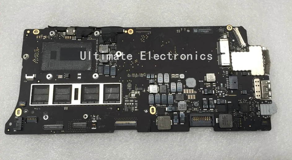
 es.aliexpress.com

15.29US $ 10% de DESCUENTO|Placa lógica defectuosa de 2015 años 820 4924 A 820 4924 para Apple MacBook Retina 13 "A1502 reparación de la placa base|Circuitos integrados| - AliExpress
¡Compra fácil, vive mejor! Aliexpress.com


