MacBook Pro 13” 2020 A2251(820-01949-07) No response to the power button.

lakykherson

New member
MacBook Pro 13” 2020 A2251
No response to the power button.

PPBUS_G3H – 12.3 V
PP20V_USBC_X_VBUS – 20.3 V

Could you please advise what should be checked before pressing the power button? And what additional measurements need to be taken?
1. PPBUS_G3H
2. PP3V3_G3H
3. PP5V_G3S
4. PP3V3_S5
5. PP1V8_S5
6. PPDCIN_G3H

Which of the above-mentioned lines should have voltage present on the board before pressing the power button, before powering on?

Or please advise what additional measurements should be taken before pressing the power button.
 
Last edited:

2informaticos

Administrator
Staff member
First of all, welcome to the forum!

Disconnect Touch ID and check if machine turns on pressing any key.
It should do it clicking trackpad also.
 

lakykherson

New member
I have already completely removed the board from the laptop. It is lying separately in the drawer. In this case, is it possible to check whether it powers on or not, or do I need to put it back into the laptop and only then check if there is a response to the power button?
 

2informaticos

Administrator
Staff member
The MLB should turns on automatically when charger is connected.
At least you should note some current variations on the USB-C meter.
 

lakykherson

New member
**What has been done:**
The board has been inspected. No signs of liquid damage were found. Under the microscope, no elements were observed that show signs of corrosion. There are no visible burn marks on the chips.

If the board is removed from the laptop and power is applied to it, the following voltages appear. However, if you take measurements on all the coils, there is no power present.

PPBUS_G3H – 12.3 V
PP20V_USBC_X_VBUS – 20.3 V
PP3V3_G3H - 3.3 V
 

lakykherson

New member
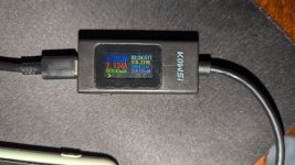
And also, I don't know why, but if I connect the power connector through the device I bought on AliExpress, which shows voltage and current consumption in amperes, it shows 5 volts. However, if I connect the cable directly to the board without this adapter and measure with a multimeter, 20 volts appear. If I connect the same device, for example, to a phone, it shows 9 volts. I am not sure whether this is an issue with this tester or with the board.2024-09-21 08.49.10.jpg


A resistance of 670 ohms on the PP20V_USBC_X_VBUS line with the board disconnected and no power applied could be a normal value?
 

2informaticos

Administrator
Staff member
Some of these testers give problems.
That's the reason I bought several models.

You should check for voltage on all big coils.
 

lakykherson

New member
I noticed an interesting detail. If I connect the power cable to the top port, the total voltage is around one and a half volts. But if I connect it to the bottom port, the voltage is normal.

Top port. PPBUS_G3H – 1.5 V
Bottom port. PPBUS_G3H – 12.3 V
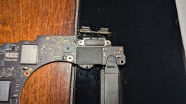
This could be related to the issue of the computer not 2024-09-21 09.37.58.jpgpowering on. How can I identify the reason why this is happening?
 
Last edited:

lakykherson

New member
If I understood correctly, I set the multimeter to diode mode, and first I connect the black probe to ground and measure the CC line with the red probe. Then, I switch the red probe to ground and measure the CC line with the black probe. The readings are approximately the same everywhere

usbc_R_cc1. 0,581. 2,43
usbc_R_cc2 0,581. 2,43

usbc_T_cc1. 0,581. 2,43
usbc_T_cc2 0,581. 2,43

usbc_W_cc1. 0,581. 2,43
usbc_W_cc2 0,581. 2,43

usbc_X_cc1. 0,581. 2,43
usbc_X_cc2 0,581. 2,43

I think these lines are fine. What else can I check?
 

lakykherson

New member
I did all the measurements without the Type-C connector cables connected. The problem could be with the Type-C connector itself; maybe it’s damaged or bent, and that’s why this is happening.
 

2informaticos

Administrator
Staff member
Don't you have USB-C connectors for test?

S-UEM2 tool is very good to test J3300_CXT/CWR.
It can also test J8500 video connector.
 

lakykherson

New member
I connected the connectors after unscrewing them from the laptop. I used a Type-C cable with one end cut off and measured the data lines through the wires. I got 0.77 on each line. It seems everything is fine
 

lakykherson

New member
I connected all the Type-C connectors again, plugged in each one, and measured the voltage. Three of them have PPBUS_G3H voltage at 12.3V, but one doesn’t have PPBUS_G3H at 12.3V.
 

lakykherson

New member
How can I test or measure the controller or the controller line responsible for the port that isn’t getting power? Could you please advise?
 

2informaticos

Administrator
Staff member
Compare diode mode readings on LDOs of CD3217 chip of bad port with the good ports.

BTW, red probe connected to ground.
We rarely need to check with black probe on ground.
 

lakykherson

New member
I measured four microchips and LDOs and found only two signals
U3100_T
PP3V3 UPC W LDO - 0,503
PP1V5 UPC LDO CORE - 0,506

U3100_X
PP3V3 UPC W LDO - 0,506
PP1V5 UPC LDO CORE - 0,512

U3100_R
PP3V3 UPC W LDO - 0,507
PP1V5 UPC LDO CORE - 0,373

U3100_W
PP3V3 UPC W LDO - 0,482
PP1V5 UPC LDO CORE - 0,285


It seems that the differences are not very critical, or are such discrepancies critical?
 
Top