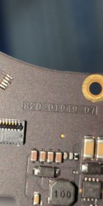
MacBook Pro 13” 2020 A2251(820-01949-07) No response to the power button.

2informaticos

Administrator
Staff member
Looks like bad U3100_W.
Is that the port where you don't get PPBUS_G3H?

Now the big problem is to get the replacement chip.
It MUST be from SAME donor board model and SAME position on the board!!!
 

lakykherson

New member
For some reason, the PP20V_USBC_X_VBUS voltage on these ports is not 20 volts, but 5 volts. This happens on all four Type-C ports.
 

lakykherson

New member
Looks like bad U3100_W.
Is that the port where you don't get PPBUS_G3H?

Now the big problem is to get the replacement chip.
It MUST be from SAME donor board model and SAME position on the board!!!

To make sure that the issue is with that port, is it possible to desolder the controller and not use this port for power, while using the remaining three ports so that the laptop can still turn on? Is it possible to test this way at all?
 

lakykherson

New member
Here’s the translation:

"Could this issue be related to this device?"

[UnionRepair U301 Data Assistant for MacBook - Read/Write, Backup & Repair](https://www.unionrepair.com/by-u301-data-assistant-for-macbook-read-write-backup-repair.html)
 

lakykherson

New member
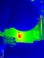
We checked with the thermal camera. This chip heats up the most. The temperatures of the other three are not significantly increasing, but this one has the highest temperature on the board. U3100_W

2024-09-21 22.31.00.jpg
 

2informaticos

Administrator
Staff member
That chip gets hotter because has problems.
You already noted that, getting lower readings on its LDOs.

The board can't turn on, nor switches to 20V on any port, if one CD3217 is bad, or missing.
You must get scrap board, as above mentioned; new chip doesn't help.
These chips have specific firmware.
 

lakykherson

New member
Just for understanding: in general, if such chips are sold separately as new, are there any programmers that can flash the required firmware? Does something like this even exist?
 

lakykherson

New member
How can I find out if this board will work for me? Here is a photo of my board; I have A2251 (820-01949-07), but in the listing, it says A2251 820-01949-A. Can you please tell me if this part will fit?

2024-09-27 19.48.55.jpg


or advise me on where I can buy this part? Do you have any links to where these parts are being sold?
 
Last edited:

lakykherson

New member
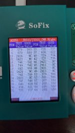
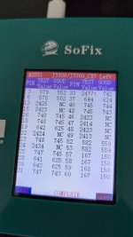
I used the device you recommended and took the measurements. Interestingly, it shows that all resistances on either the right or left connector are within the normal range. Could it be that the chip we discussed, which we suspect to be faulty, is showing normal resistance values on this connector during the measurements?
 

Attachments

  • 3300-wr.jpg
    3300-wr.jpg
    219.9 KB · Views: 5
  • 3300-XT.jpg
    3300-XT.jpg
    236.9 KB · Views: 5

2informaticos

Administrator
Staff member
The tool reports a problem (high reading) on pin 33 of J3300_CXT connector.
It corresponds to U3100_X channel.

You should check it in diode mode with multimeter.
I faced with bad contacts for the tool few times.
 

lakykherson

New member
U3100_W chip overheating, but S-UEM2 tool shows normal values – what could be the issue

I’d like to repeat my question. According to the readings from the S-UEM2 tool, the U3100_W chip (or its contacts) shows all resistance values within the expected range. However, the thermal camera shows that the chip is overheating. Could the chip still be faulty, even though all the instrument readings are normal?


I would appreciate any advice or suggestions. Thank you!
 

lakykherson

New member
I repeated the measurements using the SUEM2TOOL device. It also shows elevated resistance. I took additional measurements with a multimeter: the red probe was connected to ground, and the black probe to pin 33. In diode mode, it shows a value of 642.
 

2informaticos

Administrator
Staff member
So probably just bad contact for the tool on pin 33.

About U3100_W, it may bad, even if all indications are good.
Be aware, not all its connections go to USB connector.
 

lakykherson

New member
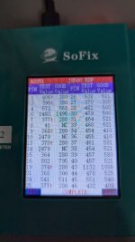
decided to take measurements using the EDP connector and found many signals that show discrepancies. An interesting question came up: why does the device show high resistance values everywhere? Or what exactly is it measuring in this case? Usually, when a device fails, the resistance values are low, but here the situation is reversed — all values are too high. I assume this might be related to a problem with the processor, based on the current readings.
 

Attachments

  • 2024-10-13 11.37.16.jpg
    2024-10-13 11.37.16.jpg
    143.4 KB · Views: 2

2informaticos

Administrator
Staff member
Higher readings than expected, can be caused by bad contacts (tool - MLB), or bad solders under the BGA chip.
In case like this, should check directly with your multimeter.
 

lakykherson

New member
Could you please clarify if the measurements are taken by resistance or by voltage drop using the diode mode? And is there a measurement chart for this model that can be used to check with a multimeter?
 

lakykherson

New member
Using the same tester and the same cable, I’m testing a donor board. All the measurements there are normal, both on the EDP and USB. But on this board, it’s showing high values on both the USB and EDP. I’ve cleaned all the contacts.
 
Top