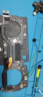
MBP 00850-A - No Power - 5.10V

mushr00m

Member
If you are not going to reply.

Just cancel my account and reimburse my money.

I registered this month to fix this macbook and makes end meet.

If the goal of the forum is not help anymore.

Just reimburse my money and cancel my account!
 

2informaticos

Administrator
Staff member
I just came back from hospital.
I spent 2 days there.
When I need to stay more time, I get may laptop and reply from hospital's bed; wasn't the case now.
 

Attachments

  • DFU + ONOFF switches 1.jpg
    DFU + ONOFF switches 1.jpg
    273.7 KB · Views: 1

mushr00m

Member
Sorry I didn't know you where at the hospital wish you recover as fast as possible.

Thanks for the image it gave me a better ideia. But can you take a closer picture showing the soldering of the pads. So I match it the same way.

Also should I turn on computer fully assembled with both SWITCH ON?
 

2informaticos

Administrator
Staff member
You should play with the switches as already explained to you days back.
Not sure what you mean with switch on; pressed maybe?

For example, DFU switch must be connected between pins 1-4, or 2-3.
The mentioned switches have 4 pins, but you can easy confirm they have only 2 connections.
Boardview also shows you 2 pins connected together, for the pads.
I can't understand your doubts...
 

Attachments

  • DFU + ONOFF switches 2.jpg
    DFU + ONOFF switches 2.jpg
    230.1 KB · Views: 1

mushr00m

Member
Still not sure about PLAYING witch switch.
You asked me to install 2 SWITCHS right?

Each switch has TWO STATES = ON and OFF.

After installd the switches what PLAYING means? turning the board with both SWITCH ON?

or you can call it PRESSED and UNPRESSED states

About your picture still far way to understand where you solder the JUMPER.

You know how to properly explain but seems you prefer to turn things more difficult, right?
 

2informaticos

Administrator
Staff member
"Press and hold down both RE030/32, release power RE030 after 5-6 s and RE032 after 3-5 s more; if DFU didn't come yet."
Similar information I gave in several other threads.
If you read only your ones, loose lot of information.
That's not recommended, if you really want to learn.

Seemed that you understood how to solder a wire on these pads; yes, or no?
That wire, can be seen as a "switch" with normal closed contact; you can open it cuting off the wire.
However, if you want to repeat the process, need to solder new wire and la-la-la.
Why don't solder a REAL switch instead, whcih its close/open states you can control, as you want???

In the schematic, RE032 has ONLY 2 lines; SOC_FORCE_DFU and P1V8_SLPS2R.
How many ways can you find to solder a switch between these TWO lines?
The schematic also shows a switch there; not soldered on the board, of course.

If you can't find the logic how to attach a switch there, is not a good idea trying to fix a MacBook board; nor any other.
I don't want to offend anybody, but this job is not easy as many people think.
 
Top