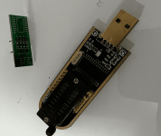
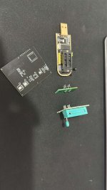
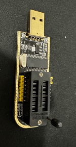
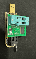
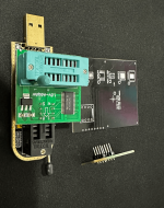
820-00850-A - Tries to turn on and restarts

mushr00m

Member
What I do have is this things.

Does not seems to be a 1.8V adapter, right?
 

Attachments

  • 2023-01-31 20_46_33-Photo - Google Photos.png
    2023-01-31 20_46_33-Photo - Google Photos.png
    445.5 KB · Views: 0

mushr00m

Member
OK. Gonna buy all of those things and follow your procedure in 2 weeks it arrive here and I will let you know!

Thank you very much!
 

mushr00m

Member
Finally arrived.

Can you give me instructions on how to assemble it?

The CH341 and 1.8V adapter I guess Its right image below!
 

Attachments

  • 55C63A66-E471-4D8D-84CE-25298AB0D8B8 (1).jpg
    55C63A66-E471-4D8D-84CE-25298AB0D8B8 (1).jpg
    640.4 KB · Views: 0

2informaticos

Administrator
Staff member
Solder the chip on the black board and insert it into 1.8V adapter.
Then insert the adapter into CH341 programmer.
Be sure to connect all properly.
Many videos and pictures should be available on Internet.
 

mushr00m

Member
I am afraid to connect the pins on the wrong position. Can you give me more guidance
 

Attachments

  • 2023-02-27 21_25_59-Photo - Google Photos.png
    2023-02-27 21_25_59-Photo - Google Photos.png
    642.1 KB · Views: 0
  • 2023-02-27 21_26_06-Photo - Google Photos.png
    2023-02-27 21_26_06-Photo - Google Photos.png
    531.3 KB · Views: 0
  • 2023-02-27 21_26_13-Photo - Google Photos.png
    2023-02-27 21_26_13-Photo - Google Photos.png
    646.8 KB · Views: 0
  • 2023-02-27 21_26_19-Photo - Google Photos.png
    2023-02-27 21_26_19-Photo - Google Photos.png
    460.9 KB · Views: 0

mushr00m

Member
Solder the chip on the black board and insert it into 1.8V adapter.
Then insert the adapter into CH341 programmer.
Be sure to connect all properly.
Many videos and pictures should be available on Internet.


I understood the basic logic
I am only not sure if I am inserting on the wrong pins
and the black board I do need to solder those pins that were soldered on the older board which I used on Macbook A1278 right?

Also the black board does not have pin numbers... not sure where to connect on the 1.8V adapter!
 

mushr00m

Member
Solder the chip on the black board and insert it into 1.8V adapter.
Then insert the adapter into CH341 programmer.
Be sure to connect all properly.
Many videos and pictures should be available on Internet.


I did NOT find a single video using the BLACK programmer
I even asked the seller to send me a video with instructions. If you have a link of at least one video/picture with instructions that would be great!
 

2informaticos

Administrator
Staff member
If I tell you pin 4 of the chip is ground, is that sufficient to find its orientation?
In fact, each pads group on the black board has pin 1 marked with white circle.

CH341 has also marked on the board position chip for 25xx series.
You've placed 1.8V adapter correctly there.

On the holes where you need to solder pins on black board, don't you think one hole has a different marking?
What pin do you think is that?
 

mushr00m

Member
If I tell you pin 4 of the chip is ground, is that sufficient to find its orientation?
In fact, each pads group on the black board has pin 1 marked with white circle.

To be honest I got confused because on the blackboard it also mentions 1.8V which is pin 8 on U4770 (PP1V8_AWAKE also image attached) so I soldered like that. Please confirm if I soldered on the right position. Always prefer to be safe than sorry asking you here


CH341 has also marked on the board position chip for 25xx series.
You've placed 1.8V adapter correctly there.

THANKS!!!

On the holes where you need to solder pins on black board, don't you think one hole has a different marking?
What pin do you think is that?

I think its PIN 4 and its GROUND but if thats TRUE the blackboard DOES NOT connect to the adapter because of the lever (image attached)

However I put the blackboard connected with the single position its could be connected using PINS.. Please also confirm

As usual prefer to be safe than sorry asking you!
 

Attachments

  • bare black board position.png
    bare black board position.png
    460.9 KB · Views: 1
  • CONSIDERING 1.8V PIN8 U4770 SOLDERED.png
    CONSIDERING 1.8V PIN8 U4770 SOLDERED.png
    623.3 KB · Views: 2
  • LEVER DO NOT ALLOW THIS POSITION.png
    LEVER DO NOT ALLOW THIS POSITION.png
    591.8 KB · Views: 2
  • ONLY POSITION USING THE PINS ON THE ADAPTER.png
    ONLY POSITION USING THE PINS ON THE ADAPTER.png
    912.4 KB · Views: 2
  • PIN 4 GND U4770.png
    PIN 4 GND U4770.png
    49.1 KB · Views: 1
  • pin 8 U4770.png
    pin 8 U4770.png
    284.5 KB · Views: 0

2informaticos

Administrator
Staff member
The black dot on the chip marks pin 1.
How can you soldered it in reverse way???

I said the circle marks pad 1 on the black board.
Apart of the (BIG) circle, pad 1 is also marked with small white dot.
 

mushr00m

Member
OK I just soldered the right way. with PIN 1 of the IC soldered on the WHITE CIRCLE

However can you explain me why PIN 4 which is GND now is connected to 1.8V WHITE name in the black board? For me it DOES NOT MAKE ANY SENSE!

Also I send you pictures of the black boards connected to the 1.8V apdater is it connected in the right way? You did not answer me this question
 

2informaticos

Administrator
Staff member
Pay more atention and put some logic.
All the group pads are connected together for the same pin.
Simple measurments can clarify you, instead of making wrong assumption.

"1.8V" is a mark for T2 ROM group pads.
Is just an warning; you can fry T2 ROM if don't use 1.8V adapter!

"black boards connected to the 1.8V apdater is it connected in the right way?"
YES.
As simple as checking if ground pin (4) of black board corresponds to 1.8V adapter ground...
 

mushr00m

Member
OK

Soldered PIN 1 to that CIRCLE (image attached) on the black board and assembled everything as I mentioned here and you confirm as right

However it does NOT detect EEPROM (image attached)

The CH341 is properly installed with driver and its working on windows. (image attached)

Whats wrong?
 

Attachments

  • 2023-03-09 19_10_50-CH341A Programmer.png
    2023-03-09 19_10_50-CH341A Programmer.png
    139.6 KB · Views: 1
  • 2023-03-09 19_11_58-Photo - Google Photos.png
    2023-03-09 19_11_58-Photo - Google Photos.png
    751.8 KB · Views: 1
  • 2023-03-09 19_11_44-Photo - Google Photos (1).png
    2023-03-09 19_11_44-Photo - Google Photos (1).png
    547.6 KB · Views: 1

mushr00m

Member
I think its the adapter I just noticed the IC on the adapter itself is getting really hot.

The position that you told me is the right one, ok?

How about that jumper on the CH341 its default when I bought it... Is it right?
 
Top