820-3115 No green light -short on PPDCIN_G3H_CHGR

Hi forgive me:

My PPBUS_g3H is now 2v. I'm not messing around with the board. I'll measure PPBUS_G3H it will be one thing, disconnect the power supply and connect again and it's another. It's weird I need to keep unplugging my charger and plugging it back in sometimes. It's like this board is messing with my charger. Once I plug and plug back in it starts to produce the right voltage? I'll try another charger or switch power strips. I'm not doing anything wierd to the board and my Soldering skills are good I would think. I've been successful with iPhone IC and Macbook SMC's just saying so that your not wondering if I'm a newb to SMD work, I'm not. I just going off what I'm experiencing don't know if this is possible or not. Maybe my power strip is going bad.. So I get 0.048 PIN 14 of U7000 and U6901 has SMC_BC_ACOK if 0.045 is high.

It would seem I have the right voltages unless SMC_BC_ACOK is not high enough. Just have to figure out where my PPBUS_G3H went
U6901
PIN 5= 3.42v
PIN 1= 0.045
PIN 2= 0.045

U7000
PIN 12 = 3.7v
PIN 2= 13.7v
PIN 3 = 3.9v
 
Last edited:

2informaticos

Administrator
Staff member
"U6901
PIN 5= 3.42v"
So now you have correct 3V42_G3H.
In the previous post you had 0V
"U6990 voltage:
Pin 6= 0.010v
------------
Pin 9 = 0.010v"
We need accurate information, try to understand.

If U7000 gets hot, is probably bad; or other surrounded component.
Post diode mode and voltage at pins 19 & 20.

The strabge thing is that you had correct PPBUS_G3H too; no idea why is lost now...
 
Yep Sorry about the incorrect posts. I got U6990 mixed up with U6900. I'll be more careful.
Not sure how you see them as an admin but I've been making edits after I see my mistake and maybe you're seeing that before I edit. Correct info is key.

U7000
Diode mode 19/20 = 0.003 both
Voltage Pin 19/20 =0.383v both

Not too sure if a Capacitor can go to ground on both ends I know an iPhone CPU cap can but I thought I'd mention right around U7000 that C7001 Pin 1 (PP5v1_CHGR_VDDP) has path to ground.
 
Replaced U7000

I have PPBUS_G3H BACK
r6905 = 16.7v
R6900 = 12.7v

U6901 has
PIN 1 = 3.3V
PIN 2 = 3.36
PIN 4 = 3.42V
PIN 5= 3.43V

NO GREEN.
 
Last edited:
U6990
Pin2 = 3.47v
Pin 3 = 14.42v
Pin4 = 16.5v

Pin 6 = 3.47v
Pin 7 = 16.5
Pin 8 = 3.47v
Pin 9 = 3.47
Pin 10 = 3.42

D6990
PIN 1 = 12.7
Pin2 = 16.7v
Pin3 = 16.4
 
Last edited:

2informaticos

Administrator
Staff member
One post back you already got 3V42_G3H
"U6901 has
---------------
PIN 5= 3.43V"
why do you bother anymore with D/U6990???

"C7005 gets hot quick"
Did you remove it, to see if short disappears?
Apart of C7000/01 remains U7000 as suspect.
 
Just posting info because I had lost some rails and I'm a newb on diagnosis of Macbook boards...:cautious: 
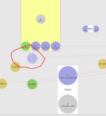
So just wanted to give you the updated info after replacing U7000. Just wanted to be thorough.
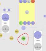
The last post was after replacing U7000
And the short on c700/1 went away. Also C7005 is not getting hot quick. And all of the voltages in the last post are current.
 
Last edited:
Voltages @ U7000

1 = 0.004
2 = 16.7
3 = 3.93
4 = 3.46
5 = 1.2
6 = 3.47
7 = 0.89
8 = 2.06
9 = 0.031
10 = 3.46
11 = 3.47
12 = 3.44
13 = 3.45
14 = 3.42
15 = .072
16 = 12.2
17 = 12.2
18 = 12.2
19 = 5.07
20 = 5.05
21 = 0.22
22 = GND
23 = 12.2
24 = 12.5
25 = 16.5
26 = 16.5
27 = 16.27
28 = 16.28

U7000 Diode Mode

1 = 0.622
2 = 0.607
3 = 0.508
4 = 0.509
5 = 0.702
6 = 0.678
7 = 0.718
8 = 0.512
9 = 0.707
10 = 0.499
11 = 0.499
12 = 0.341
13 = 0.463
14 = 0.458
15 = 0.719
16 = 0.646
17 = 0.425
18 = 0.431
19 = 0.444
20 = 0.445
21 = 0.443
22 = GND
23 = 0.430
24 = 0.830
25 = 0.576
26 = 0.620
27 = 0.613
28 = 0.606

Thank you for the help. I've really learned so much.
 

2informaticos

Administrator
Staff member
So now you have 12.2V at PPBUS_G3H.
Check SMC_RESET_L and diode mode to ground at SCL/SDA lines of battery bus.
 
J6950 Diode mode

Pin 4 = 0.499 (SMBUS_SMC_5_G3_SCL)
Pin 5 = 0.499 (SMBUS_SMC_5_G3_SDA)

Acutually I'm not too sure where to measure SMC_RESET_L

So here goes:

U5010
Pin 5 = 3.44v

R7000
PIN 1 = 3.44V

The test point in the attached picture = 0.0v
 

Attachments

  • Test point.png
    Test point.png
    54.8 KB · Views: 0

2informaticos

Administrator
Staff member
Post again exact PPBUS_G3H voltage; 12.2V is not the same as 12.5V.
Do you have green light now?
3V3_S5 present?
 
I'll post a couple spots as I'm not confident where I should be testing but if you tell me once I'll remember.

PPBUS_G3H @
R6905 = 12.23v

F7040 = 12.22 PIN 1/2

R4264 = 12.24
Q4262 = 12.24 Pin 4
F9700 = 12.24

C3338 = 12.24
R3880 = 12.24
q5480 = 12.23
R5481 = 12.23

Q4260 = 12.23
C4260 = 12.24
R4260 = 12.24

R5410 = 12.24

I hope that's not too overkill.
 
Ok sorry won't happen again. Just didn't know if there might be some difference at different points and if that would help you out or not. I appreciate the schooling. Thx. oops forgot 3V3_S5 one sec.
 
Top